24 034, 036, 036 QS
– Remove the piston - see 5.3.1.
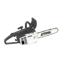
– Remove rings from piston.
Use a piece of old piston ring to
scrape the grooves clean.
Warning:
VA
138RA043
Do not install 1.2 mm rings in
pistons with 1.5 mm grooves.
Install the new piston rings in the
grooves so that the radii at the
ends of the rings face upward.
– Install the piston - see 5.3.2.
VA
138RA044
– Remove the chain brake - see 4.4
and 4.5.
– Remove the oil pump - see 11.4
– Remove the flywheel - see 6.4.1
– Remove the ignition module - see
VA
138RA045
6.5.1
– On machines with handle and/or
carburetor heating, remove the
generator - see 10.5.1.
– Remove the cylinder and piston -
see 5.3.1.
– Remove the tank housing - see
12.8.1.
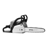
– Remove the spiked bumper.
Use a 5 mm drift or other suitable
tool to drive out the two dowel
pins from the clutch side.
Unscrew the five mounting
screws which join the two halves
of the crankcase.
VA
138RA046
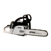
Use a screwdriver to rotate the
spur gear clockwise until the
tensioner slide butts against the
thrust pad.
Note:
Use service tools
AS 5910 007 2205 and
148RA086
VA
ZS 5910 007 2200 to remove and
install the crankshaft. Follow the
instructions supplied with the tools.
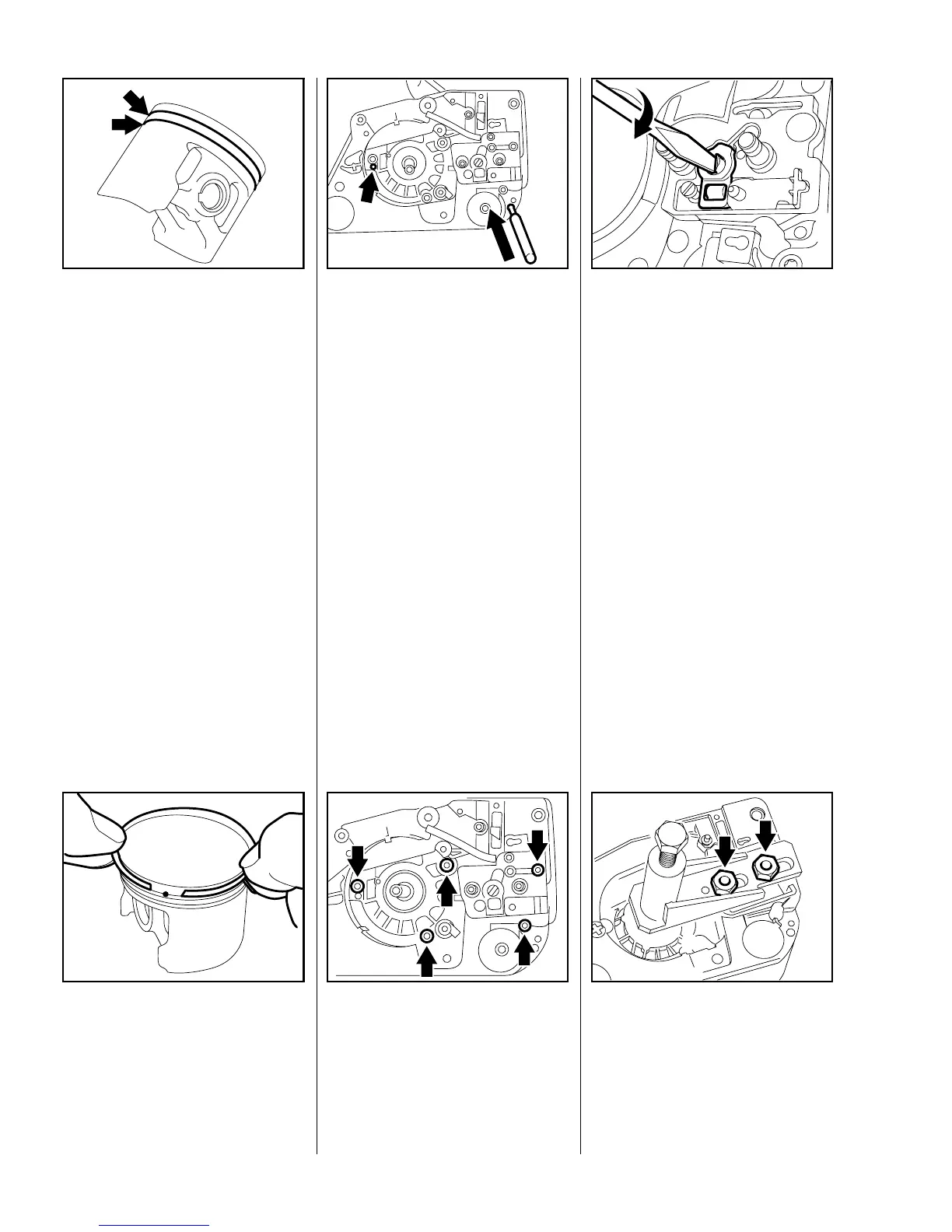
– Back off spindle on service tool
AS all the way.
Slip service tool
AS 5910 007 2205 over the two
collar studs, fit the hexagon nuts
(for sprocket cover) and tighten
them down by hand.
VA
138RA047
5.4 Piston Rings 5.5 Crankcase
5.5.1 Removing the Crankshaft
 Loading...