39034, 036, 036 QS
The ignition module accommodates
all the components required to
control ignition timing.
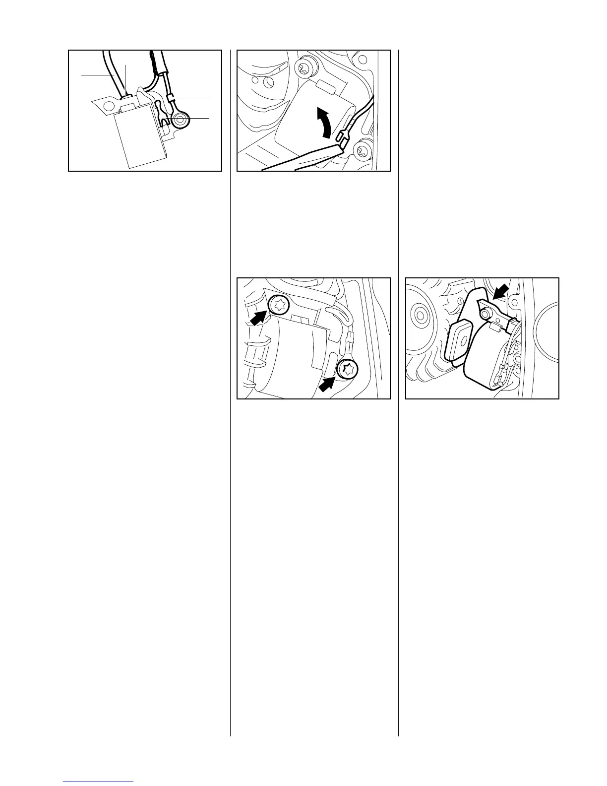
Ignition module components and
connections
1 Ignition lead with insulating tube
VA
138RA103
1
4
3
2
2 High voltage output
3 Ground wire
4 Connector tag for
short circuit wire
Accurate testing of the ignition
module is only possible with special
test equipment. For this reason it is
only necessary to carry out a spark
test in the workshop.
A new ignition module must be
installed if no ignition spark is
obtained (after checking that wiring
and stop switch are in good
condition).
– Remove the fan housing - see
6.4.1
Use a screwdriver to disconnect
the short circuit wire from the
ignition module.
VA
138RA104
Take out the two mounting
screws and lift away the ignition
module.
Note:
If the ignition module is faulty,
unscrew the ignition lead
counterclockwise and transfer it
VA
138RA105
along with the spark plug boot and
cable retainer to the new ignition
module.
– To install the ignition module,
connect short circuit wire to tag
on ignition module and then push
the short circuit wire into the
retainer.
– Place the ignition module in the
crankcase.
– Coat threads of ignition module
mounting screws with LOCTITE -
see 13.2.
– Use lower mounting screw to
connect the ground wire to the
ignition module.
Fit the two screws and tighten
them down moderately.
– Rotate the flywheel until the
magnets are between the two
arms of the ignition module.
Slide the setting gauge
1111 890 6400 or 0.2 mm metal
gauge between the arms of the
ignition module and the flywheel
magnets.
– Press the ignition module against
the flywheel and tighten down the
VA
138RA107
mounting screws (see
"Tightening Torques").
Important:
Tighten the upper screw first.
– Remove the setting gauge and
use a feeler gauge to check the
air gap. It should be 0.2 to
0.3 mm.
– Fit the fan housing - observe
tightening torques (see
"Tightening Torques").
6.5 Ignition Module 6.5.1 Removing and Installing
 Loading...