ELECTRICAL 4-21
7 N
.
m
(0.7 kg-m)
(5.1 lb-ft)
5.5 N
.
m
(0.55 kg-m)
(4.0 lb-ft)
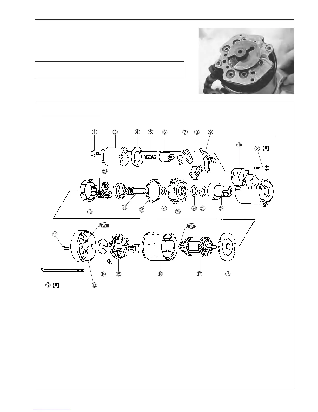
ASSEMBLY
Assembly is reverse order of disassembly with special atten-
tion to the following steps.
When installing armature, exericise care to avoid
breaking brushes.
When installing pinion shift lever, refer to figure in construction
diagram for its installation direction.
1 1
1 1
1 Nut
2 2
2 2
2 Bolt
3 3
3 3
3 Magnetic switch
4 4
4 4
4 Gasket
5 5
5 5
5 Spring
6 6
6 6
6 Plunger
7 7
7 7
7 Torsion spring
8 8
8 8
8 Rubber packing
9 9
9 9
9 Shift lever
0 0
0 0
0 Front housing
A A
A A
A Screw
B B
B B
B Through bolt
C C
C C
C Rear cover
D D
D D
D Thrust washer
E E
E E
E Brush holder
F F
F F
F Yoke
G G
G G
G Armature
H H
H H
H Center cover plate
I I
I I
I Internal gear
J J
J J
J Planetary gear
K K
K K
K Pinion shaft
L L
L L
L Pinion
M M
M M
M E-ring
N N
N N
N Washer
O O
O O
O Center bracket
P P
P P
P Rubber ring
Construction diagram
1
 Loading...


