3-20 ENGINE CONTROL SYSTEM
AIR INTAKE COMPONENTS
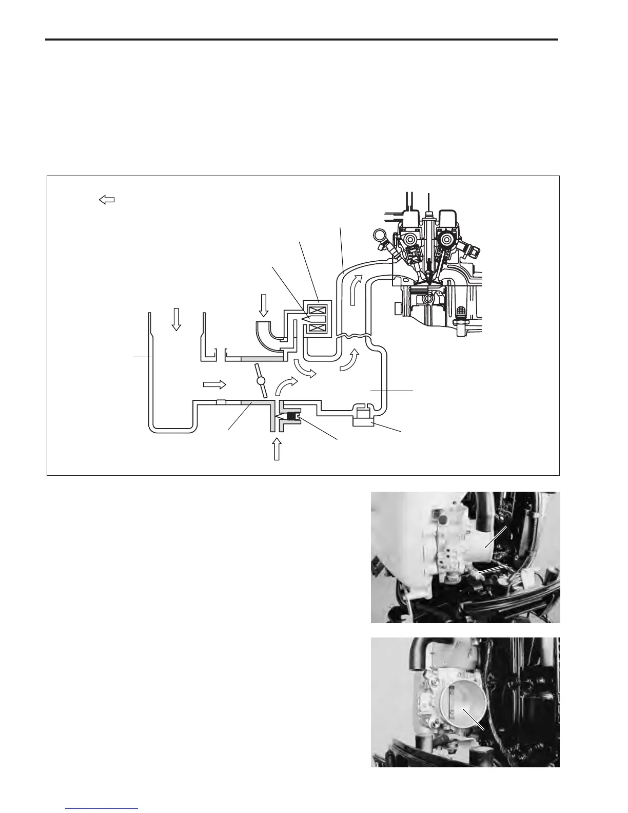
Air, after entering through the silencer, passes through the throttle body and flows into the surge tank where
it is then distributed to the cylinder intake manifold.
Intake manifold pressure, monitored by the MAP sensor, is an indirect measure of the intake air amount.
When the throttle is fully closed, the main supply of intake manifold air necessary to sustain engine idle
passes through the by-pass air passage.
To maintain engine idle speed at specification, the ECM controlled IAC valve supplies a regulated amount of
additional air through the IAC (idle air control) passage.
THROTTLE BODY
The throttle body assembly consists of the main bore, throttle
valve, by-pass air passage, by-pass air screw and CTP switch.
The throttle body adjusts the intake air amount with the throttle
valve which is connected to the throttle / linkage lever.
The CTP (closed throttle position) switch installed on the bot-
tom of throttle body informs of throttle valve position.
NOTE:
Do not try to adjust or remove any of the throttle body compo-
nent parts (CTP switch, throttle valve, throttle / linkage lever,
etc.).
These components have been factory adjusted to precise speci-
fications.
Throttle bodyThrottle body
CTP switchCTP switch
Throttle valveThrottle valve
Intake
manifold
Throttle
body
Silencer
IAC valve
Valve
By-pass
air screw
MAP sensor
Surge tank
: Air flow
 Loading...


