13-22 DF90/115/140 “K3” (‘03) MODEL
W
1
W
2
W
3
W
B
W
1
W
2
W
3
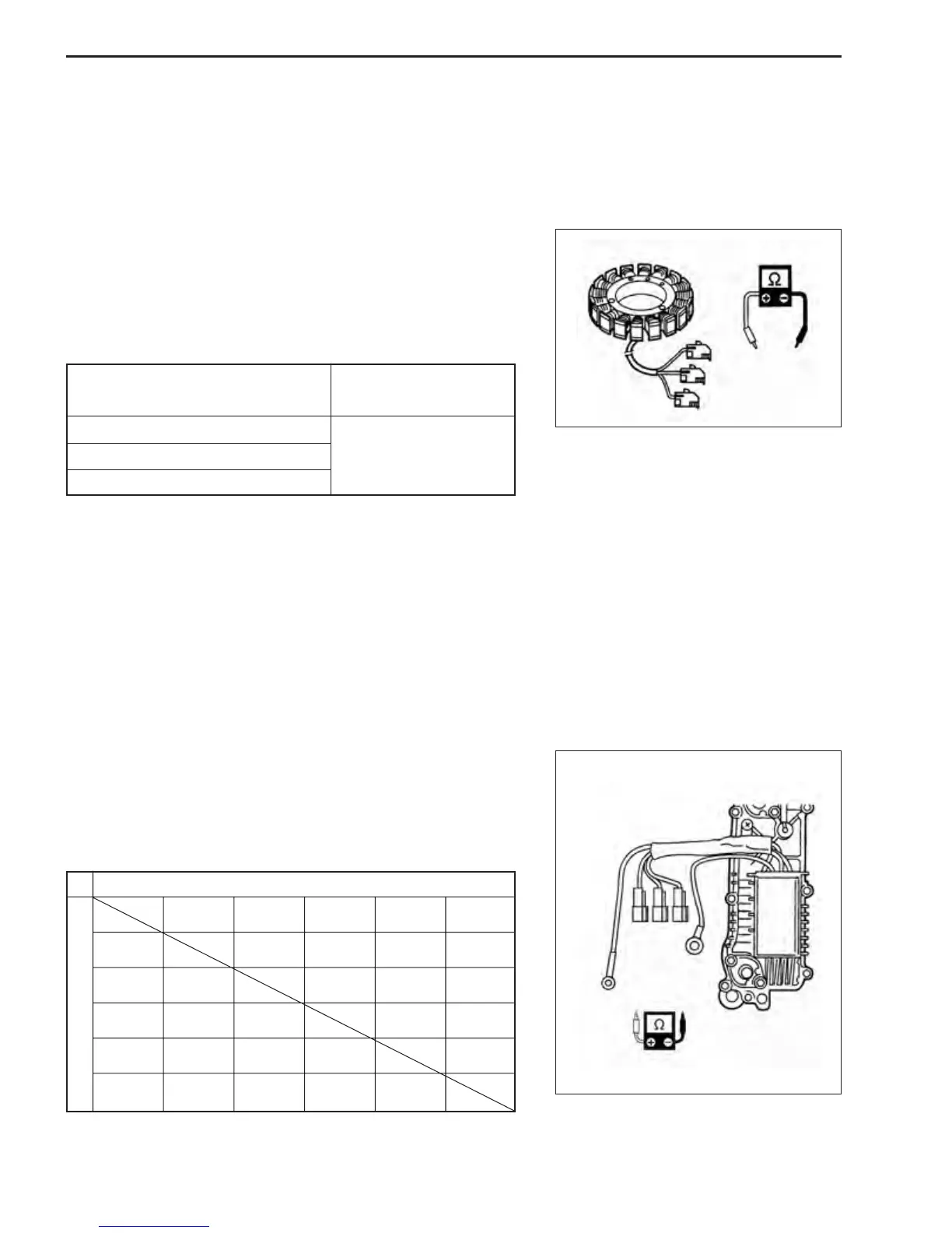
BATTERY CHARGE COIL
Battery charge coil has been changed in shape of connector.
Measure battery charge coil resistance.
\ 09930-99320 : Digital tester
V Tester range :
ΩΩ
ΩΩ
Ω (Resistance)
1. Disconnect battery charge coil leads from rectifier & regula-
tor.
2. Measure resistance between leads in the combinations
shown.
Battery charge coil resistance :
Terminal for tester probe
connection
Resistance
White
1 to White 2
White 2 to White 3
White 3 to White 1
0.16 – 0.24 Ω
RECTIFIER & REGULATOR
Rectifire & Regulator has been changed in shape of connector.
\ 09900-25010 : Pocket tester
V Tester range : ×1 k
ΩΩ
ΩΩ
Ω (Resistance)
1. Disconnect all lead wires of rectifier & regulator.
2. Measure resistance between leads in combinations shown.
NOTE:
The values given below are for a SUZUKI pocket tester.
As thyristors, diodes, etc. are used inside this rectifier & regula-
tor, the resistance values will differ when an ohmmeter other than
SUZUKI pocket tester is used.
Tester probe + (Red)
Tester probe - (Black)
Black White
White 1
White 2
White 3
Black
White
White 1
White 2
Unit : k
ΩΩ
ΩΩ
Ω
0.5~10
0.5~10
4~80
4~80
3~60
1~20
5~100
5~1005~100
5~100
4~804~804~80
0.5~1000.5~1000.5~100
White 3
0.5~104~80 5~1005~100
If measurement exceeds specification, replace rectifier & regula-
tor.
If out of specification, replace battery charge coil.
Rectifier & regulator resistance :
 Loading...


