DF90/115/140 “K8” (’08) MODEL
18-25
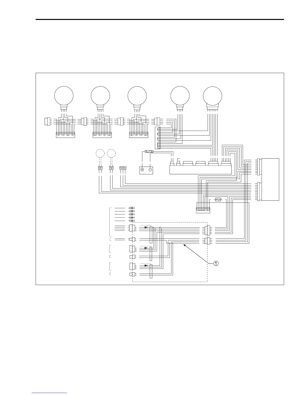
NOTE:
• In the case that the wiring harness gauge connector is connected to the SDS communication connector,
SDS (SUZUKI Diagnosis System) cannot be used.
• When SDS has to be used, disconnect the SDS communication connector from the gauge connector.
• When SDS is being used, the digital gauge system cannot be operated.
NOTE:
• The remote control wire should be connected to the interface module harness adaptor with the specified
connector as shown below. If the remote control wire is not connected to the specified connector of the
interface module harness, the meter will not function properly.
• Single engine: Connect to label (P) connector.
• Twin engine:
PORT engine: Connect to label (P) connector.
STBD engine: Connect to label (S) connector.
B
B
W
W
B
B
W
W
B
B
W
W
B
B
W
W
B
B
W
W
B
B
W
W
B
B
W
W
B
B
W
W
B
B
W
W
B
Y
L
R/W
R/W
L
Y
B
B
Y
L
R/W
B
R
W
R
B
B
B
B
B
W
W
W
B
B
R
Gr
R/W
L
Y
B
R
B
W
B
B
W
W
W
W
B B
B
B
W
W
P/B
P/W
B
P
R
B
G
Gr
Gr
Gr
B
Gr
B
G
R
W
Gr
B
G
R
W
W/Y
W/G
W/B
B
W/Y
W/L
W/B
B/W
R/G
Gr
Y
B
B
G/Y
G/W
L/B
P
Gr
B
G
W/Y
B
W/Y
B/W
Gr
B
R
W/L
B/W
Gr
B
W
W/B
B/W
W/Y
W/G
W/B
B
B
W
W
B
B
Gr
G
B
R
P
B
P/W
P/B
B
G
R
W
Main fuel
sensor
Sub fuel
sensor
Battery
Active hub unit
1. Voltage meter
2. Fuel gauge
3. Trim gauge
4. Speedometer
5. Tachometer
Remote control wire (PORT)
Trim sender connector (PORT)
Remote control wire (Center)
Trim sender connector (Center)
Remote control wire (STBD)
Trim sender connector (STBD)
123 45
Interface
module
P
C
S
Label (S)
Label (C)
Label (P)
DIGITAL GAUGE WIRING DIAGRAM
Interface module
harness adaptor
 Loading...


