ENGINE 3-21
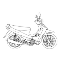
• Remove the valve from the combustion chamber side.
• Remove the valve stem seal
1.
• Remove the valve spring seat
2.
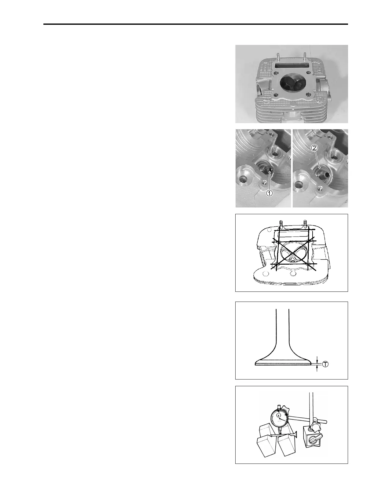
CYLINDER HEAD DISTORTION
Decarbon the combustion chamber.
Check the gasket surface of the cylinder head for distortion
using a straightedge and thickness gauge. Take clearance read-
ings at several places. If readings exceed the service limit,
replace the cylinder head.
$ Cylinder head distortion
Service Limit: 0.05 mm (0.002 in)
& 09900-20803: Thickness gauge
VALVE FACE WEAR
The thickness of the valve face decreases as the face wears.
Visually inspect each valve face for wear and replace any valve
with an abnormally worn face. Measure the valve face thickness
T, if it is out of specification, replace the valve with a new one.
$ Valve head thickness
Service Limit: 0.5 mm (0.002 in)
& 09900-20101: Venier calipers
VALVE STEM RUNOUT
Support the valve using V-blocks, as shown, and measure its
runout with the dial gauge. If the runout exceeds the limit,
replace the valve.
$ Valve stem runout
Service Limit: 0.05 mm (0.002 in)
& 09900-20606: Dial gauge (1/100 mm)
09900-20701: Magnetic stand
09900-21304: V-block (100 mm)

 Loading...