102
6
7
ICS VALVE
3
5
4
2
1
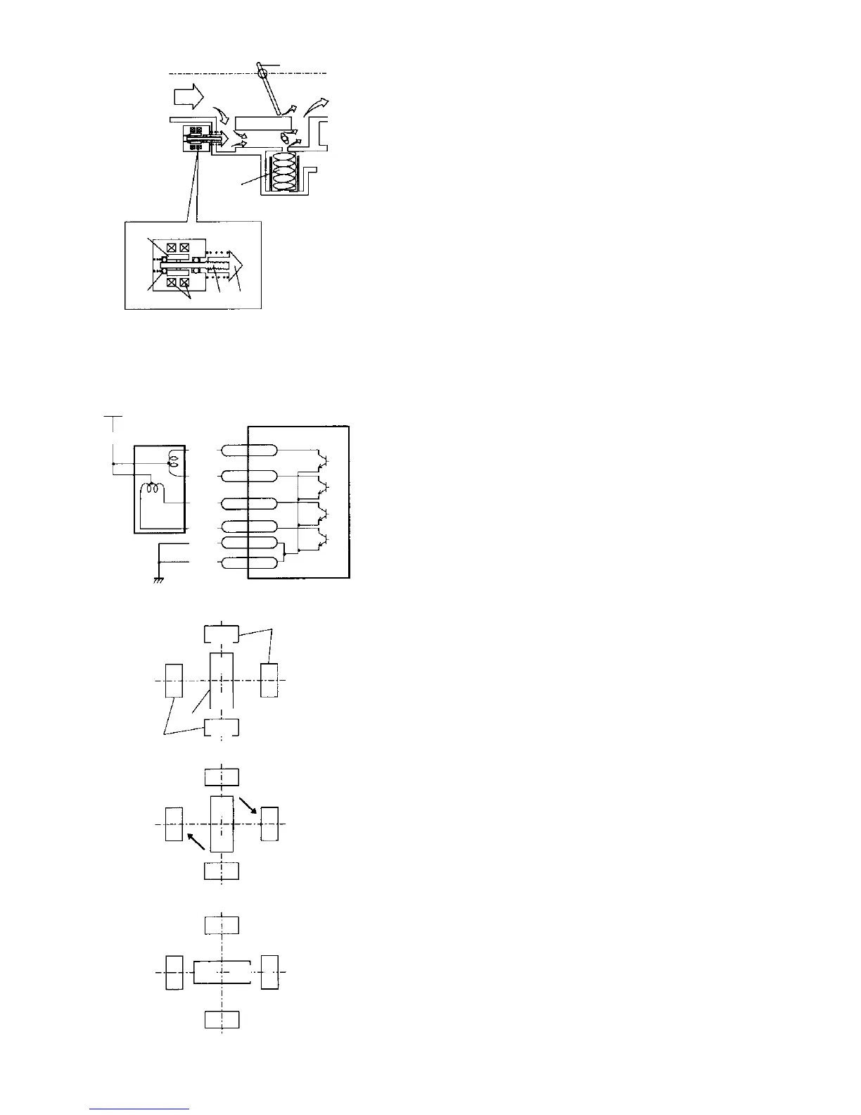
1. VALVE PINTLE
2. SCREW SHAFT
3. MAGNET (ROTOR)
4. COIL
5. BEARING
6. THROTTLE VALVE
7. BIMETAL TYPE
LIMITER VALVE
+12V
(VIA RELAY)
B/R
ISC VALVE
11
SMA
12 SMB
13
SMC
14
SMD
9 E01
E1
17
ECM
R/B
R
R/Y
R/BL
B/BL
B
COLOR CODE
B – BLACK
R – RED
Y – YELLOW
BL – BLUE
N
S
S
N
8
8
9
STATUS (1)
S
N
SN
SUCTION
FORCE
SUCTION
FORCE
STATUS (2) STATOR SWITCHING
SN
S
N
STATUS (3) ROTOR ROTATION
8. STATOR
9. ROTOR
ISC Valve
The ISC valve controls the bypass air amount and
stabilizes the idling rpm.
The ISC valve is installed on the throttle body and
uses a stepper motor system.
The transistor for driving the ISC valve in the ECM
receives an instruction from the CPU and switches
ON or OFF, the step motor in the ISC valve rotates a
number of steps proportional to the instruction, driv-
ing the valve, thereby the bypass passage is opened
or closed, and the engine is controlled to the target
idling rpm. The stepper motor rotates using the mag-
netic attraction of a stator and rotor. When the
excitation of the stator is switched from the state (1)
in the figure to the left, becoming state (2), torque in
the magnetic rotational direction is produced in the
rotor, and a stable position is achieved in state (3) by
the rotation of the rotor. (The figure to the left shows
the operating principle of the stator rotor and may be
different from that actually used. The actual system
uses two–phase excitation.) By repeating this, the
rotor turns in a number of steps according to the
instruction of the ECM, the rotation is converted to
torque (extension–contraction) via a screw shaft,
and the ISC flow amount is changed by the stroke of
the valve pintle.
A battery voltage is fed to the center terminal of the
two coils from the main relay when the ignition
switch is ON, and the two end terminals are each
connected to the ”SMA~D” terminals of the ECM.
The voltage of the ”SMA~D” terminals of the ECM is
under 1 V when connected, and otherwise is the bat-
tery voltage.
 Loading...


