EasyManua.ls Logo

Suzuki F6A User Manual

Suzuki F6A
202 pages
To Next Page IconTo Next Page
To Previous Page IconTo Previous Page
Page #6 background imageLoading...
Page #6 background image
4
Input circuit
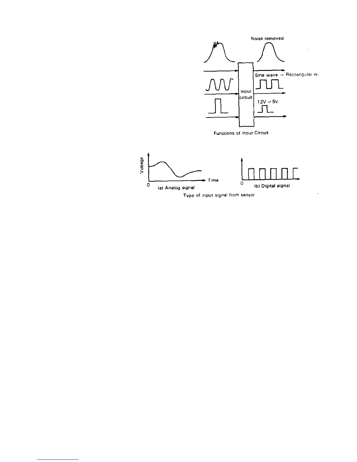
When a signal from each sensor enters ECM, it first passes
through the input circuit, where any noise on each signal is
removed and a sine wave signal such as a crank angle signal is
converted to a pulse signal (rectanglar wave). Another function of
the input circuit is to convert the voltage level of the digital signal
to such voltage level that can be processed by the microcom-
puter which operates at a 5V voltage.
A/D Converter
The analog signal received by the ECM
must be converted into a digital signal
for microcomputer processing and this
conversion is done by the A/D con-
verter.
Microcomputer
The microcomputer accepts signals from the sensors as necessary, processes them by using programs and data written
in it and then sends the results to the output circuit as fuel injection signals, ignition signals, etc. Here each of its compo-
nents is described.
(1) CPU
CPU is the brain of the microcomputer. It processes the input data by using the processing program stored in the ROM.
In the CPU, simultaneous processing of a large amount of data is not expected, for the data is processed one by one
within each unit time. However, as the processing speed is as high as to handle over one million operations per second, it
can process a large amount of data very quickly.
(2) Memory (ROM, RAM)
The ROM (Read–Only Memory) is where programs and data necessary for control are stored. Once stored in it, they are
retained as they are, even if power has been turned OFF and no change can be made to them.
The RAM (Random Access Memory) is where input data and processed results are temporarily stored. They will be
erased if power is turned OFF.
(3) Input/output interface
The input/output interface controls receiving and sending signals according to the command from CPU. As CPU cannot
process a large amount of data simultaneously as described above, inputting/ outputing of signals is executed according
to the programmed sequence.
Output circuit
As the output signal from the microcomputer is a digital signal, it cannot operate the actuator. The output circuit has a
function to operate the actuator, based on the output signal from the microcomputor.

Table of Contents

Question and Answer IconNeed help?

Do you have a question about the Suzuki F6A and is the answer not in the manual?

Suzuki F6A Specifications

General IconGeneral
Displacement657 cc
Cooling SystemWater-cooled
Bore x Stroke65.0 mm x 66.0 mm
Compression Ratio8.5:1
Fuel SystemCarburetor or Fuel Injection
Maximum Torque57 Nm (42 lb-ft) at 4, 000 rpm
ValvetrainSOHC
Engine TypeInline 3-cylinder

Summary

SECTION 2: PERIODIC MAINTENANCE

Alternator Belt Inspection

Inspect and adjust alternator belt tension for proper operation and alignment.

SECTION 3: TROUBLE SHOOTING

SECTION 4: ENGINE MECHANICS

Crankshaft and Connecting Rods

Details the crankshaft and connecting rods, their construction, and specifications for engine performance.

Pistons, Rings, and Pins

Covers piston, piston ring, and piston pin specifications, including dimensions and materials.

Timing Belt and Pulleys

Describes the belt drive system, timing marks, tensioner, and pulley specifications for synchronization.

Lubrication System

Outlines the engine lubrication system, oil flow, and components for proper lubrication.

SECTION 5: ENGINE REPAIR

Engine Lubrication Details

Details the engine oil circulation path, pump operation, and oil pressure relief.

SECTION 6: ENGINE CONTROL SYSTEM

System Wiring Diagram

Provides a detailed wiring diagram for the EFI system, showing connections and color codes.

Fuel System Components

Details the components of the fuel system, including tank, pump, filter, and injectors.

Diagnosis and Troubleshooting

Explains self-diagnosis, code retrieval, and troubleshooting procedures for the engine control system.

SECTION 8: IGNITION SYSTEM

Ignition Coil and Spark Plugs

Explains ignition coils, spark plugs, their testing, and replacement procedures.

Ignition Timing Control

Describes ignition timing adjustments for different modes and corrections based on engine conditions.

SECTION 9: FUEL SYSTEM

SECTION 11: CRANKING SYSTEM

SECTION 12: CHARGING SYSTEM

SECTION 13: SPEED LIMITER

SECTION 14: CHASSIS

SECTION 15: TRANSMISSION AUTOMATIC

Hydraulic Mechanism and Control

Details the valve body, hydraulic pressure distribution, control solenoids, and gearshift control logic.

Diagnosis and Trouble Codes

Explains the diagnosis function, code retrieval, and a table of diagnostic trouble codes and failsafe actions.

Related product manuals