195
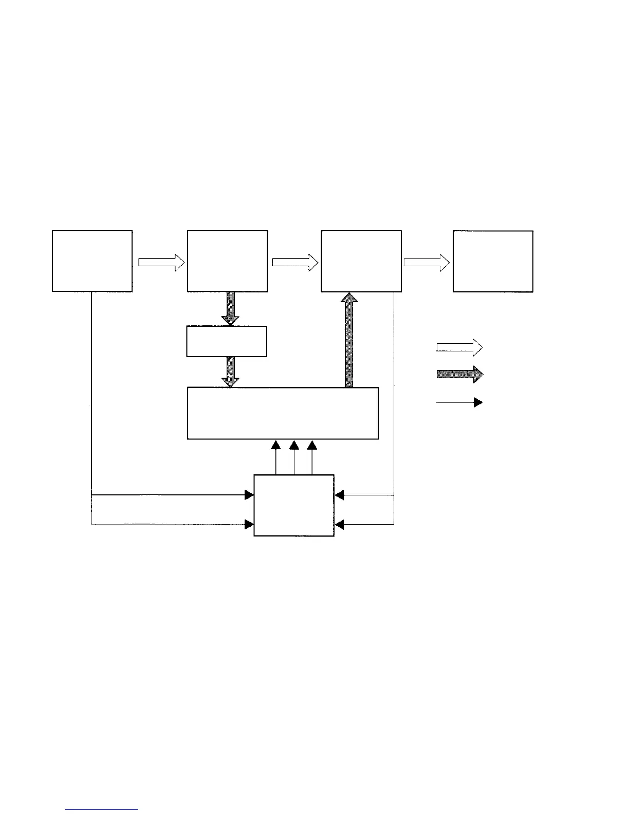
CONTROL MECHANISM
GEARSHIFT CONTROL
Shifting in the EPI models is performed using shift solenoid valves No. 1 and No. 2, which are controlled by the AT
controller that is integrated with the EPI controller, and in manual valve that is controlled by the selector lever.
When the selector lever is in neutral at P or N, or reverse in R, mechanical shifting is performed by the manual valve
and line pressure.
In other ranges, shifting up and shifting down into or from 1
st
, 2
nd
or 3
rd
gear is performed by the shift solenoid valves
No. 1 and No. 2.
Please refer to the preceding pages for the power transmission path and hydraulic circuit for each change of gears.
EG
TORQUE
CONVERTER
SPEED
CHANGER
DIFFERENTIAL
GEAR
OIL PUMP
OIL PRESSURE CONTROL DEVICE
SHIFT SOLENOID SIGNALS
NO. 1, NO. 2, NO. 3
THROTTLE SIGNAL
WATER TEMPERATURE SIGNAL
EPI & AT
CONTROLLER
VEHICLE
SPEED
SIGNAL
SHIFT SW
SIGNAL
DRIVE FORCE
OIL PRESSURE
SIGNAL
 Loading...


