187
HYDRAULIC MECHANISM
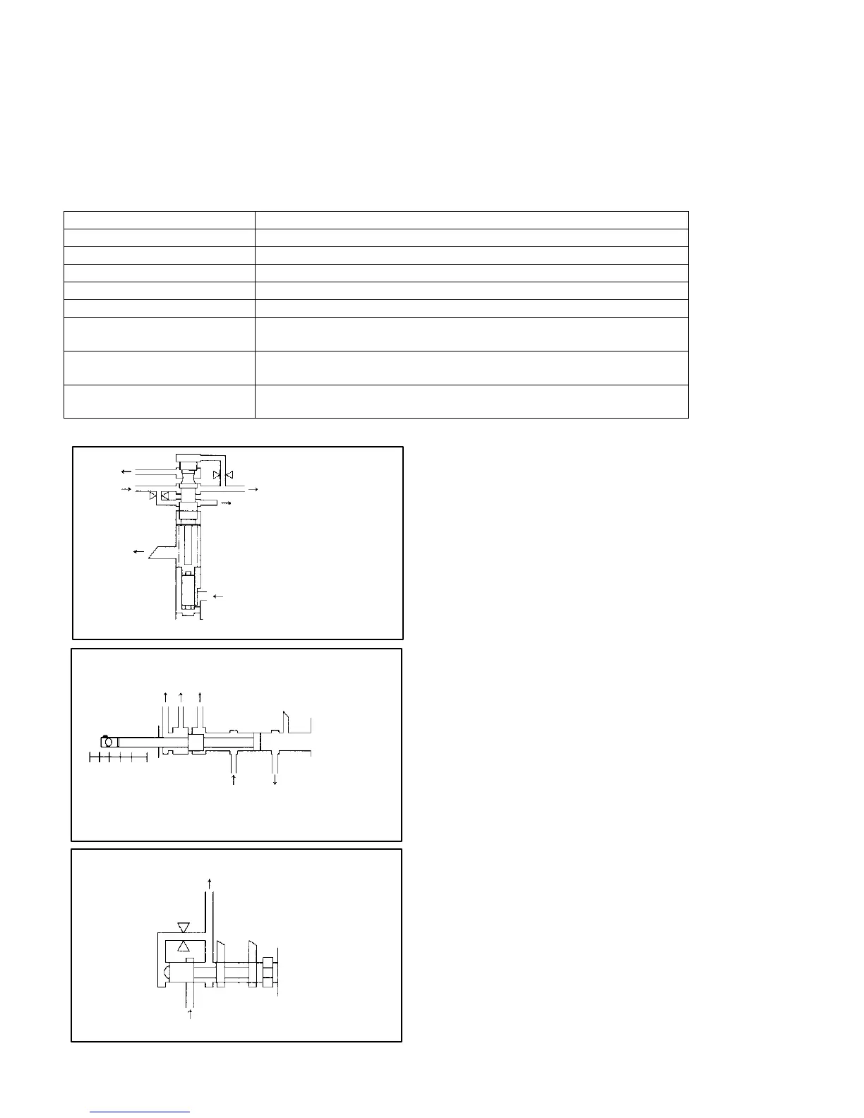
VALVE BODY
The valve body distributes the hydraulic pressure generated by the oil pump to the clutch and brake.
Internally, is comprised of a manifold valve, which distributes the basic hydraulic pressure, shift valves, which switch
hydraulic pressure to the clutch and brake, pressure regulator valve, which adjusts the line pressure, accumulator,
which absorbs the shift shock, etc.
The oil pathway is provided on the main body, and the shift pumps are operated by means of shift solenoid valves.
Valve name Function
Pressure regulator valve Regulates line pressure according to running status
Locust modulator valve Regulates line pressure applied to 1st reverse brake
Manual valve Distributes line pressure according to position of selector lever
1–2 shift valve Performs shifting from 1
st
to 2
nd
gear
2–3 shift valve Performs shifting from 2
nd
to 3
rd
gear
Shift solenoid valve No. 1
(direct clutch solenoid)
Opens and closes drain port by solenoid, switches line pressure to
1–2 shift valve
Shift solenoid valve No. 2
(direct clutch solenoid)
Opens and closes drain port by solenoid, switches line pressure to
2–3 shift valve
Shift solenoid valve No. 3
(direct clutch solenoid)
Acts as a damper when second brake band servo is operating
DRAIN
OIL
PAN
DRAIN
MANUAL VALVE
ACCUMULATOR
TORQUE CONVERTER
MANUAL VALVE [R] RANGE
2–3 SHIFT VALVE
DRAIN
SHIFT SOLENOIDS NO. 1, NO. 2
FORWARD CLUTCH
PRESSURE
REGULATOR
VALVE
L2DN P
PRESSURE REGULATOR
VALVE DIRECT CLUTCH
FIRST REVERSE BRAKE
2–3 SHIFT VALVE
VALVES AND SOLENOIDS
PRESSURE REGULATOR VALVE
This valve adjusts the hydraulic pressure gener-
ated by the oil pump to a designated pressure (line
pressure). The hydraulic pressure changes
according to the running range.
MANUAL VALVE
This valve switches the direct line pressure
according to the selector lever.
LOCOST MODULATOR VALVE
This valve absorbs shock so that the increase in oil
pressure is dampened when line pressure is
applied to the first reverse brake in the L range and
R range.
 Loading...


