167
See your authorized CUSHMAN dealer for nec-
essary maintenance and service.
• When replacement parts are required, use genu-
ine CUSHMAN parts or parts with equivalent
characteristics including type, strength and
material. Failure to do so may result in product
malfunction and possible injury to the operator
and/or bystanders.
• Immediately replace any warning decal that
becomes hard to read.
MAINTENANCE GUIDE
The guide is set up for average use on clean, paved sur-
faces. Vehicles used in dusty areas, for winter driving or
in wet, snowy or muddy conditions require more frequent
service.
AS REQUIRED
Check tire pressure
Check self adjusting brakes
EVERY 200 HOURS OF OPERATION
Perform previous Services
Lubricate all grease fittings *
Check differential oil level **
EVERY 1000 HOURS OR YEARLY
Perform previous Services
Change differential oil **
Clean and repack front wheel bearings
* Refer to the lubrication chart.
** The differential oil must be changed after the FIRST
100 hours or 1000 miles of service.
BRAKE FLUID
Use type Dot (3). . . . . . . . . . . . . . . . . . . . . . . . . . . . . . . .
Access to the master cylinder is through the opening in
the floorboard in front of the operators seat.
LUBRICATING BRAKE PEDAL BUSHING
The brake pedal pivot bushing lubrication fitting is
located just below the hole in the floorboard, near the
brake pedal. See Figure 5.
Pedal Lubrication Access Hole
FIGURE 5
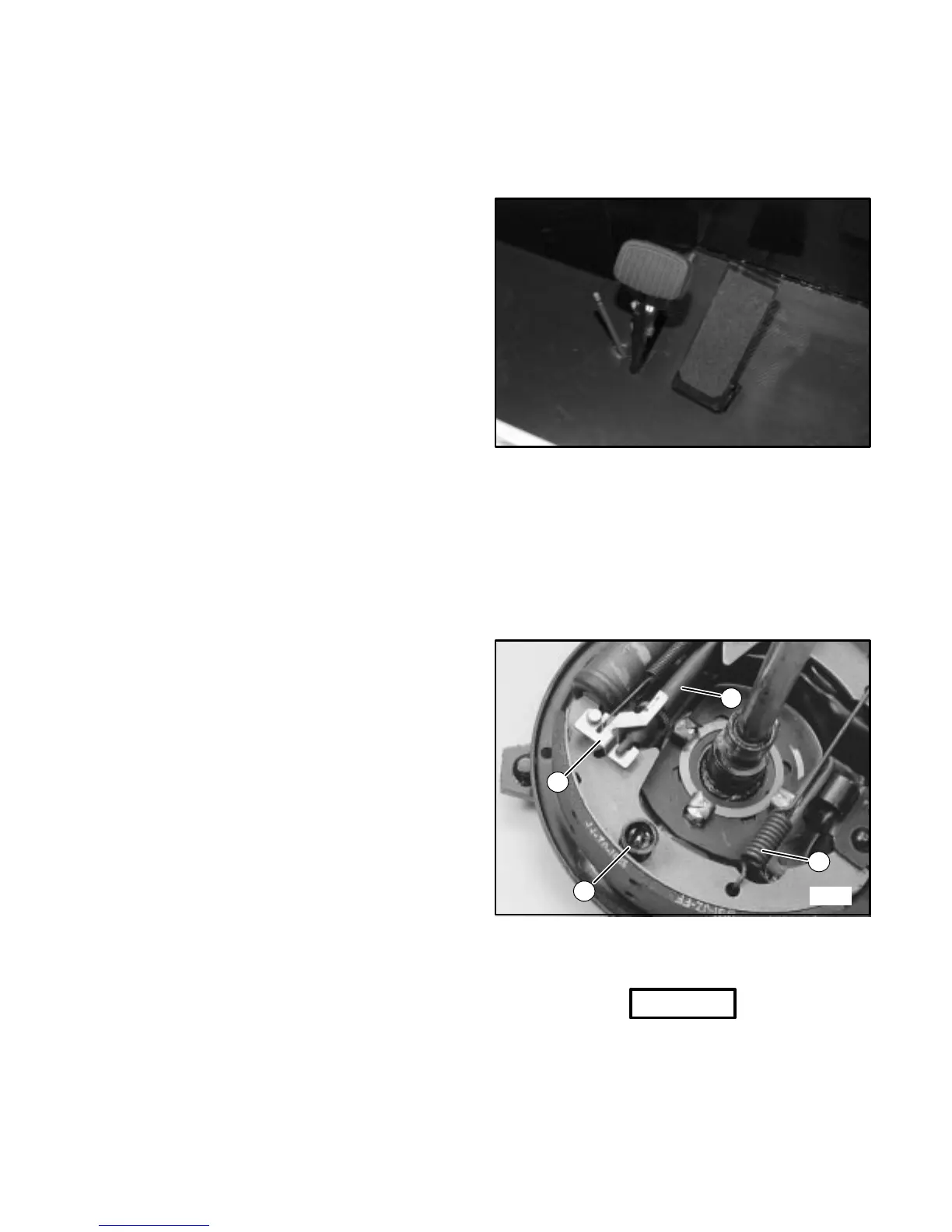
BRAKE SHOE REPLACEMENT
1. Remove the front wheel and hub assembly.
2. Disconnect both return springs from shoe assembly
and brake lever. Remove shoe retainers. Remove
brake lever and adjuster. Care must be taken not to
disturb the hydraulic wheel cylinder. Remove the
brake shoes from the backing plate. See Figure 6.
1
2
3
4
4406
FIGURE 6
1. Brake Lever 3. Return Springs
2. Shoe Retainers 4. Brake Adjuster
NOTICE
• DO NOT press the brake pedal while the brake is dis-
assembled.
• Examine the wheel cylinder for leaks before reas-
sembly by carefully pulling back each rubber boot on