168
the wheel cylinder. Fluid present in the boot area
indicates a leaking wheel cylinder. Refer to Figure 7.
3. Clean the brake backing plate.
Reassembly
4. Apply a thin layer of high temperature lubricant to the
brake backing plate where the brake shoes make
contact (6 places) and brake adjuster. See Figure 7.
1
1
2
3
3
4396
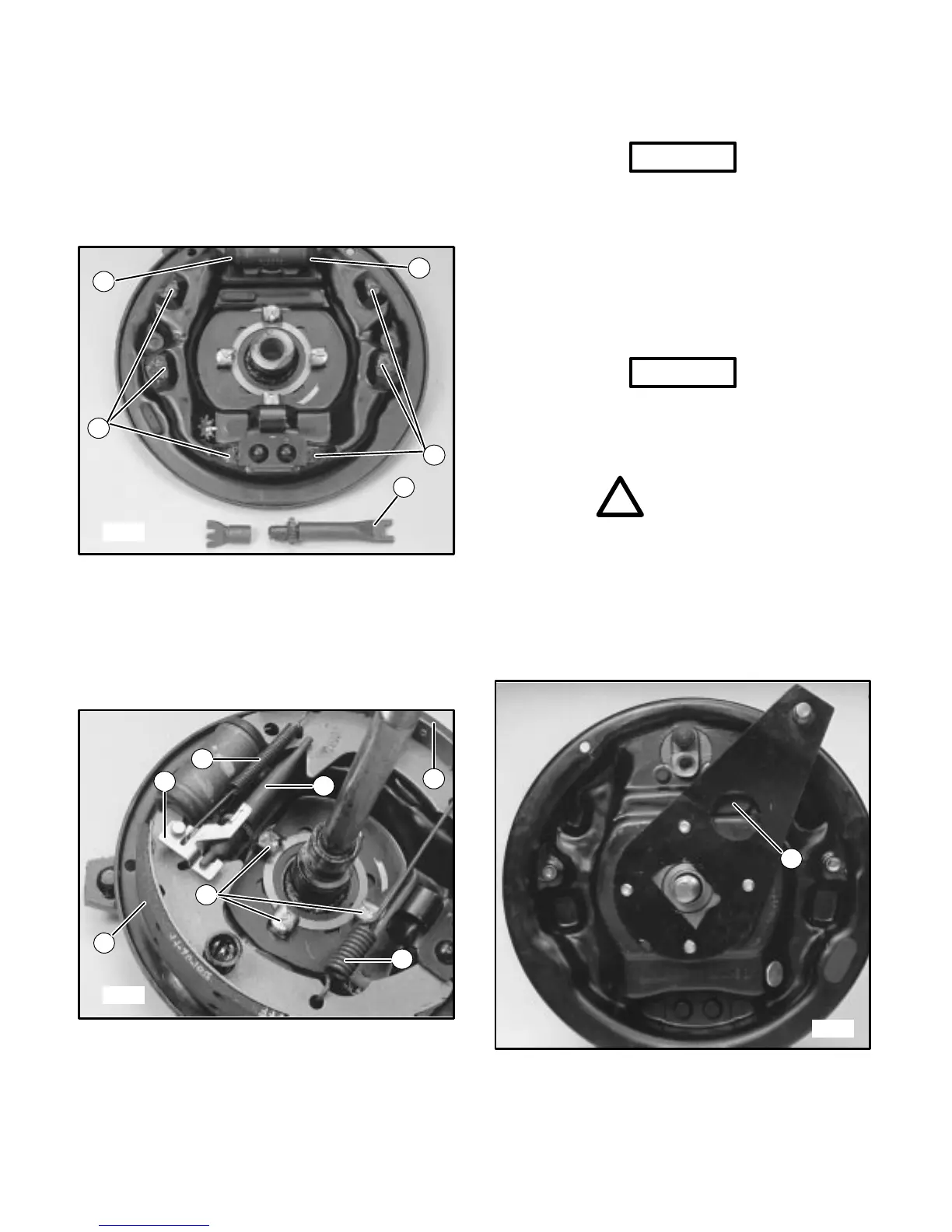
FIGURE 7
1. Brake Shoe Contact Pads (6)
2. Brake Adjuster
3. Wheel Cylinder Rubber Boots
5. Install brake shoes and brake adjuster. See Figure 8.
1
2
3
4
5
6
1
4406
FIGURE 8
1. Brake Shoe
2. Brake Adjuster
3. Small Retainer
Spring
4. Large Retainer Spring
5. Brake Retainers
6. Brake Lever
6. Install brake retainers, brake lever and small retainer
spring. Install larger retainer spring. See Figure 8 on
page 16.
NOTICE
• Note position of brake lever and small retainer
spring. See Figure 8 on page 16.
7. Install new seals, clean and repack wheel bearings
with a lithium based lubricant. Install wheel bearings
then install wheel assembly onto vehicle. Refer to
front wheel bearing section for correct procedure.
FRONT BRAKE ADJUSTMENT
NOTICE
• This brake is self adjusting and needs adjustment
only on initial installation.
1. Raise the vehicle off the ground.
WARNING
!
• Support the vehicle on approved jackstands, to
prevent it from falling and causing injury. DO
NOT rely on hydraulic or mechanical jacks to
support the vehicle while working on or under it.
2. Remove adjusting hole cover from brake dust shield.
See Figure 9.
1
4400
FIGURE 9
1. Adjusting Hole Cover
3. Using a flat blade screwdriver, turn the adjusting
wheel up (screwdriver handle down) to adjust brake

 Loading...


