112
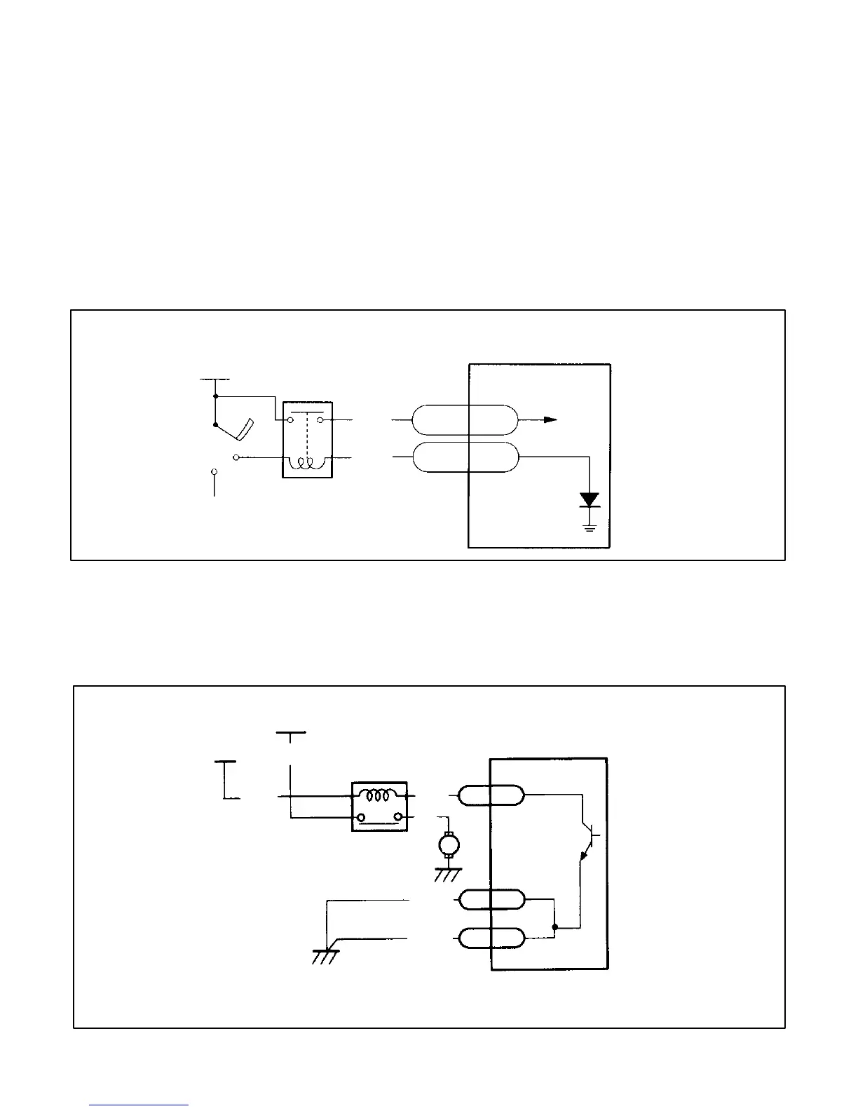
MAIN RELAY CONTROL
The main relay supplies battery voltage to the ECM according to the ON/OFF status of the ignition switch.
When the ignition switch is turned ON, the coil of the relay is ground, and thereby the relay switch circuit is closed.
By this means, battery voltage is applied to the ”+B” terminal, and the EFI system is activated.
Further, the output circuit of the relay supplies battery voltage to the following actuators and sensors.
Actuators and servers using the main relay as a power source
• Injectors • ISC valves • Crank angle sensor
• Vehicle speed sensor • Radiator fan relay (coil side) • Fuel Pump
The circuit of the relay coil is connected to a ground via a diode in the ECM, and prevents current from running through
the coil in the unlikely event of reverse connection of the battery.
+12V (BAT.)
IGSW
ST
IG1
MAIN RELAY
B/R
GY/W
201
207
+B
RG
12V
ECM
COLOR CODE
B – BLACK
R – RED
G – GREEN
W – WHITE
GY – GRAY
FUEL PUMP RELAY CONTROL
The ON/OFF control of the fuel pump is performed by the ECM controlling the fuel pump relay (controlling current
flowing to the relay coil part). When the relay is ON, battery voltage is applied to the fuel pump, and the pump is operated.
The fuel pump operates under the following conditions.
+12V
(VIA MAIN RELAY)
IG1 R/B
W/G
FUEL PUMP
RELAY
B/BL
ECM
PK/B
4 FPR
M
FUEL PUMP
B/BL
B
9
E01
E02
17
COLOR CODE
B – BLACK
PK – PINK
BL – BLUE
W – WHITE
G – GREEN
 Loading...


