178
3584
1
2
3
4
5
6
7
8
9
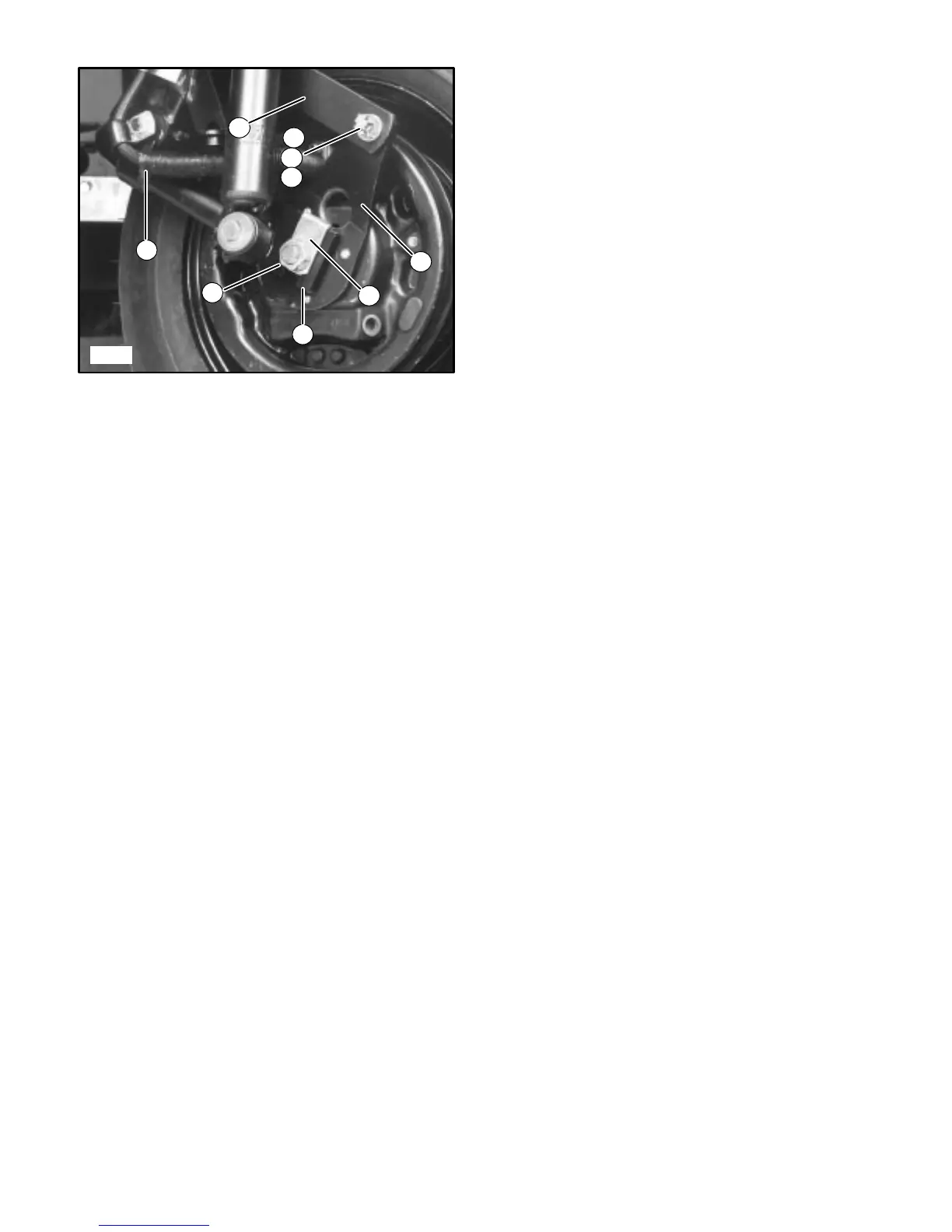
Front Wheel (Brake Side)
FIGURE 24
1. Front Fork Side Arm
2. Brake Anchor Link
3. Brake Arm
4. Cotter Pin
5. Castle Nut
6. Washer
7. Axle Nut & Lockwasher
8. Axle Lock
9. Brake Hose and Protector
Brake Link Bushings (not shown, refer to
SAFETY WARNING regarding Brake Link
Bushings at the bottom of page 26, column 2).
Large Flat Washer (not shown, refer to rein-
stallation procedure).
Remove the hub, brake and axle as follows:
• DO NOT disconnect the brake hose.
• Remove the cotter pins, washers and castle nuts
attaching the brake anchor link to the front fork and
brake arm. Discard the cotter pins.
• Pull the link straight off the mounting studs. Retain
the bushing located in the hole at each end of the
brake anchor link.
• Disassemble the LEFT shock absorber attaching
hardware and the lower end of the shock absorber.
Note position of all parts.
• Loosen the axle nuts and lower the entire hub, brake
and axle assembly from the front fork. Remove the
wheel retaining nuts.
• Position and support the brake hose and protector to
avoid damage while the wheel, hub and axle are
being assembled.

 Loading...


