4-32 FI SYSTEM DIAGNOSIS
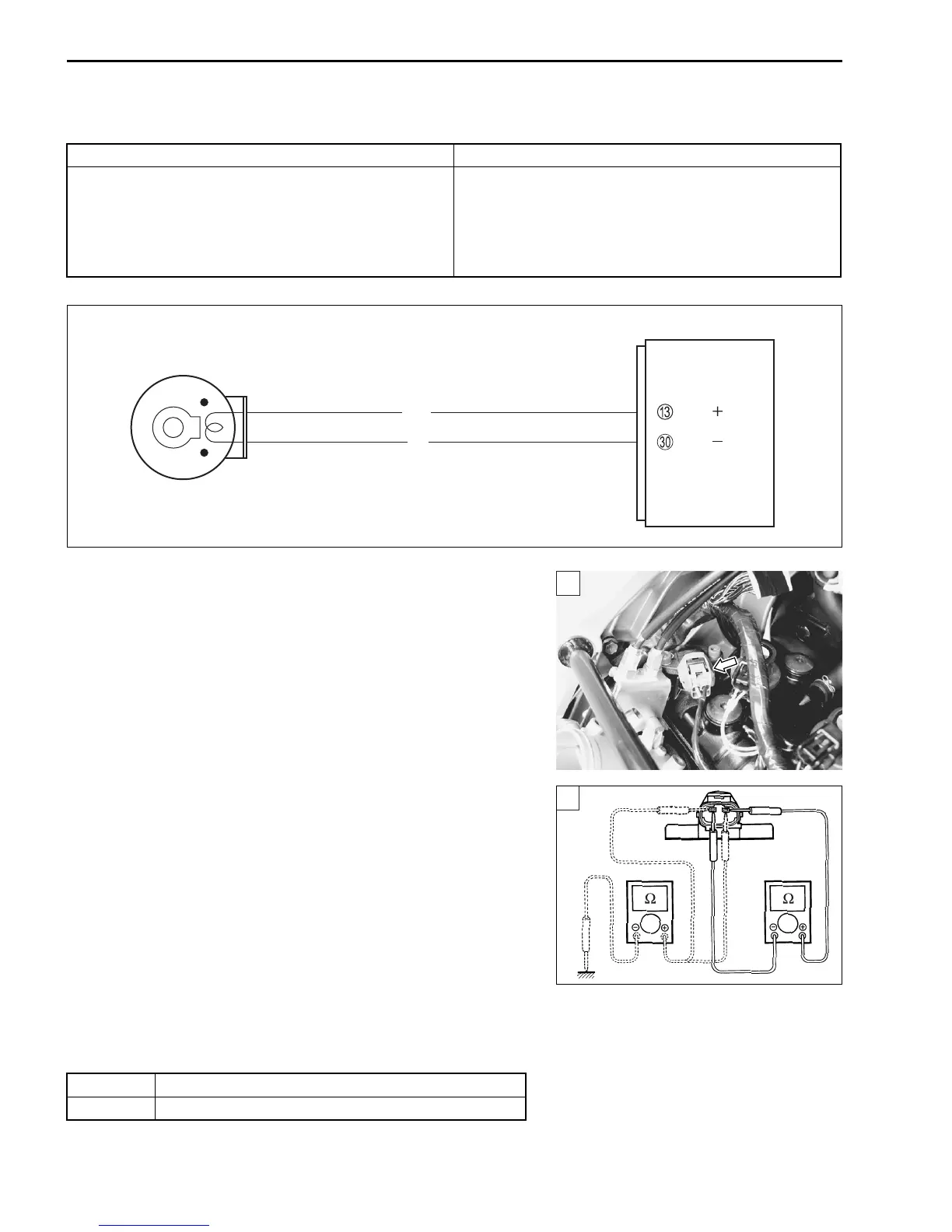
“C11” (P0340) CMP SENSOR CIRCUIT MALFUNCTION
INSPECTION
Step 1
1) Turn the ignition switch to OFF.
2) Lift and support the fuel tank. (5-3)
3) Remove the air cleaner box. (5-13)
4) Check the CMP sensor coupler for loose or poor contacts.
If OK, then measure the CMP sensor resistance.
5) Disconnect the CMP sensor coupler and measure the resis-
tance.
CMP sensor resistance: 0.9 – 1.7 kΩ
(Terminal – Terminal)
09900-25008: Multi-circuit tester set
Tester knob indication: Resistance (Ω)
6) If OK, then check the continuity between each terminal and
ground.
CMP sensor continuity: ∞ Ω (Infinity)
(Terminal – Ground)
Are the resistance and continuity OK?
7) After repairing the trouble, clear the DTC using SDS tool.
(4-26)
DETECTED CONDITION POSSIBLE CAUSE
The signal does not reach ECM for 3 sec. or more,
after receiving the starter signal.
• Metal particles or foreign material being stuck on
the CMP sensor and rotor tip
• CMP sensor circuit open or short
• CMP sensor malfunction
• ECM malfunction
ECM
CMP sensor
CMP
CMP
G/Y
Br
1
YES Go to step 2.
NO Replace the CMP sensor with a new one.
1

 Loading...