25
HYDRAULIC SYSTEM
Overview
The hydraulic system in the Synesso™ is comprised of all parts through which water ows starng with
where it enters the machine from the water treatment/ltraon system. This chapter will detail the ow of
water and some of the associated electrical components.
Synesso ulizes 3/8” braided stainless hoses (supplied with the machine) to connect to the water treatment
system. Once the machine is set up and the water quality is checked, the machine is ready to connect to the
water treatment system. The water then passes to the pump and motor.
On single pump and motor machines, water for the brew boiler goes through the pump and the water for
the steam boiler travels through a separate line to the steam tank ll valve. The next 2 pages show the dual
inlet system and MVP Hydra inlet water paths.
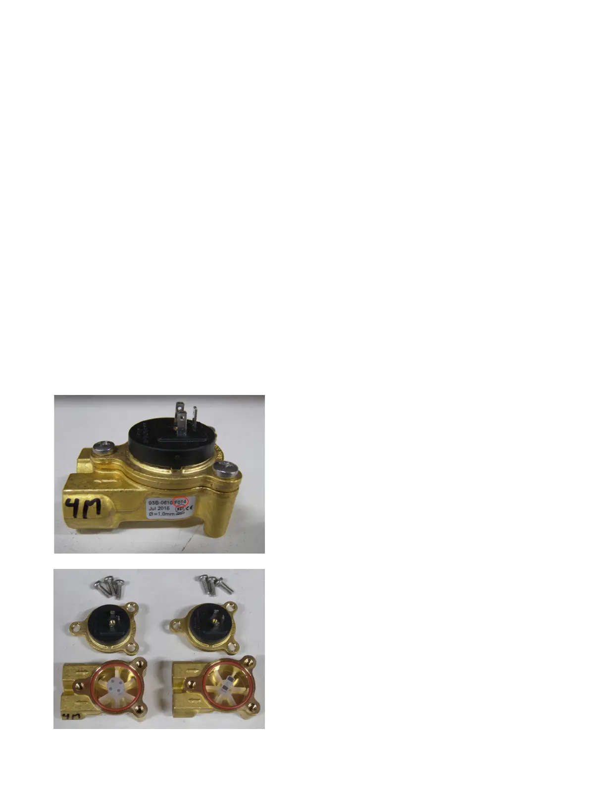
The 4 Magnet Flow Meter is shown on the LEFT
The 2 Magnet Flow Meter is shown on the RIGHT
HYDRAULIC COMPONENTS
Flow Meters:
The MVP and MVP Hydra incorporate high precision 4 magnet ow meters. Flow meters act as counng de-
vices for the incoming cold water that routes to each brew group. These devices are essenal to the volu-
metric control of the MVP Series machines.
Previous machines have ulized 2 magnet ow meters.
While the outward appearance is idencal, the label
part number for the current 4 magnet ow meters
ends in “14”. The two magnet and four magnet ow
meters are NOT interchangeable.

 Loading...