37
ELECTRICAL SYSTEM
Hall Eect Board Replacement Guide:
1. Turn o machine.
2. Unplug 4-pin connector from back of board.
3. Remove two #6-32 nuts and two #6 washers.
4. Li board o of mounng posts.
5. Lower replacement board over posts.
6. Replace washers and loosely thread on nuts.
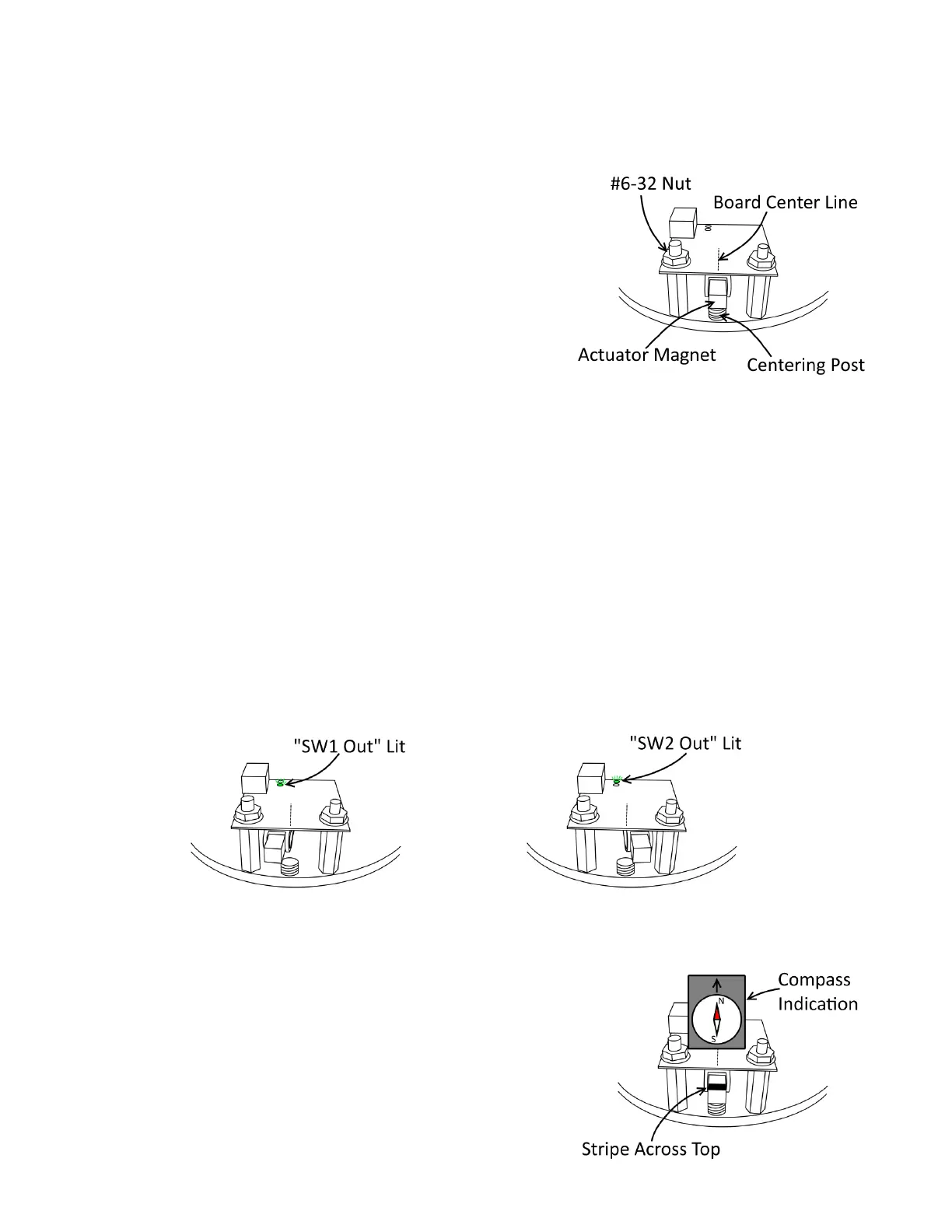
7. Rotate actuator unl Actuator Magnet is perfectly centered over
Centering Post.
8. Align Board Center Line mark with Actuator Magnet center as close-
ly as possible.
9. Tighten nuts.
10. Reconnect 4-pin connector to new board.
11. Turn machine back on and test trip points as follows:
a. Very slowly turn actuator clockwise, watching the “SW1 Out” LED towards the back of the board. The LED
should light at some point before the actuator magnet reaches the far le posion.
b. Slowly allow the actuator to return to center. The “SW1 Out” LED should turn back o before the actuator
reaches its center resng posion (note that the actuator will never quite return to the exact center on its
own, though it should get fairly close.)
c. Slowly turn the actuator counter-clockwise, watching the “SW2 Out” LED. The LED should light at some
point before the actuator magnet reaches the far right posion.
d. Slowly allow the actuator to return to center. The “SW2 Out” LED should turn back o before the actuator
reaches its center resng posion.
Actuator Magnet Replacement Note:
For the Hall Eect Board to read the Actuator Magnet posion,
the magnet must be oriented properly. Replacement magnets
will come marked with a solid stripe on the top face of the mag-
net. Magnet orientaon can also be veried with a compass as
shown to the right.

 Loading...