Home
Technics
Electronic Keyboard
SX-KN7000P
Technics SX-KN7000P User Manual
5
of 1
of 1 rating
160 pages
Give review
Manual
Specs
To Next Page
To Next Page
To Previous Page
To Previous Page
Loading...
7.
Disassembly
Instructions
7.1.
Removing
the
top
cabinet
1.
Turn
the
keyboard
cabinet
upside
down,
and
remove
the
bottom
screws
(
17
pcs.)
as
shown
in
Fig.2
.
2.
Place
the
keyboard
bottomside
down,
and
open
the
top
cabinet
.
Fig.2
11
10
12
Table of Contents
Specifications
2
Performance Pads
4
Auto Play Chord
4
Safety Precaution
8
Insulation Resistance Test
9
Owners Manual
9
MIDI Implementation Chart
10
Keyboard Ranges
10
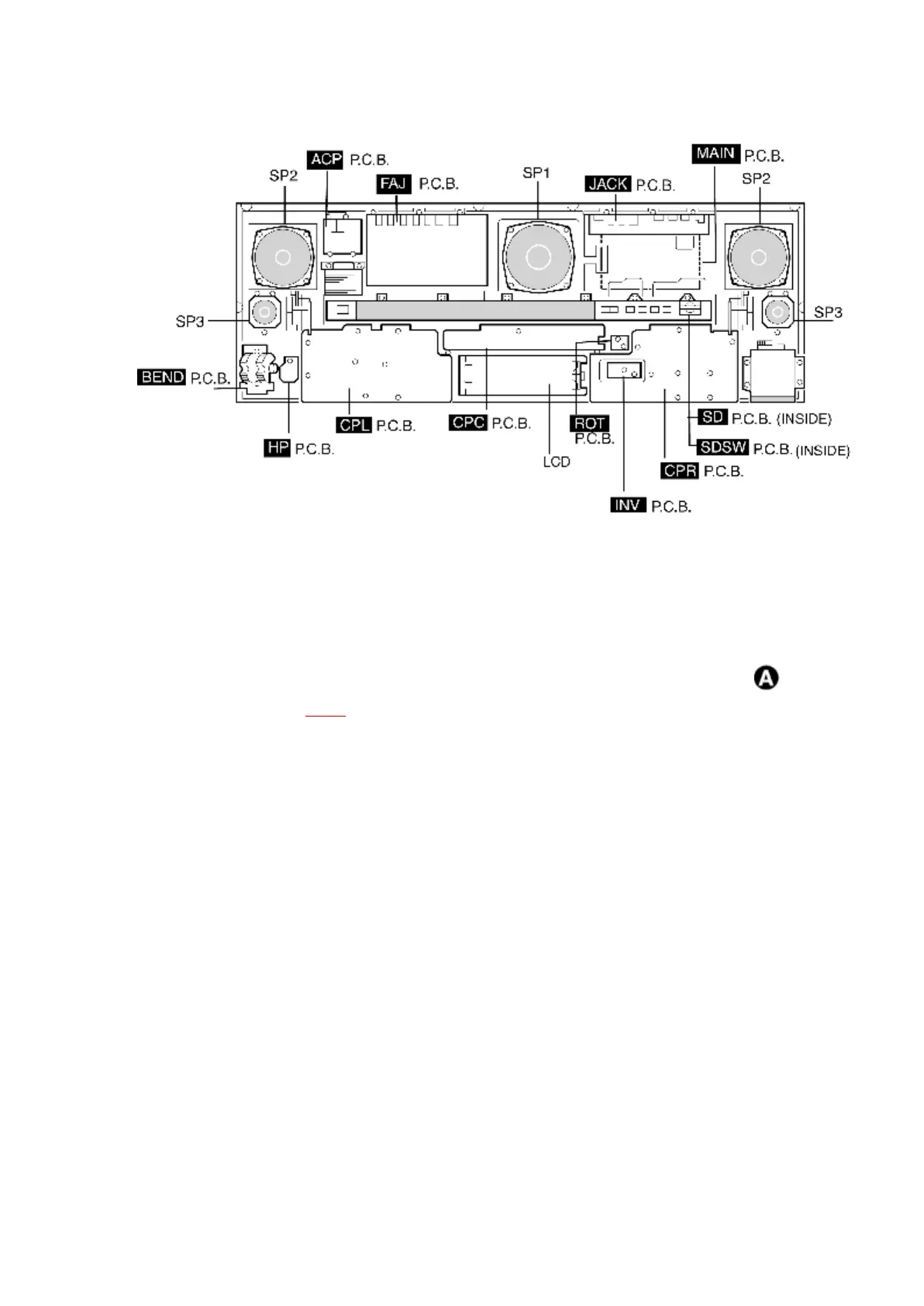
Parts Location
10
Disassembly Instructions
11
Removing the Top Cabinet
11
Net Panel and Keyboard Unit
13
Control Panel
13
Power SW Panel
13
SD Panel
13
Keyboard Unit
14
Removing the JACK and MAIN Printed Circuit Boards
14
Jack P.C.b.
14
Main P.C.b.
15
Removing the FAJ Printed Circuit Board
16
Faj P.C.b.
16
ASUB P.C.B. Disasemble
17
ASUB P.C.B. Asemble
17
Removing the ACP Printed Circuit Board
18
Acp P.C.b.
18
Pcs.) as Shown in Fig
18
Lcd
20
Cpl P.C.b.
20
Cpr P.C.b.
20
ROT P.C.B. , CPC P.C.B. and INV P.C.B
20
Removing the SD and SDSW Printed Circuit Boards
21
Removing the BEND and the HP P.C.B.
22
Removing the Disk Drive Unit
23
Removing the Power SW
24
Removing the 14Cm SP, 12Cm SP and 6.5Cm SP
25
Removing the Keys
26
Service Diagnostic Function
27
To Set to the Service Diagnostic Mode
27
ROM Device Test
28
RAM Device Test
29
Floppy Disk SAVE/LOAD Test
30
Panel SW & LED Test
31
In & out Interface Test
32
Rgbwb
32
Crosstalk
32
Sample
32
MIDI IN/OUT Test
33
WAVE ROM Test
34
SOUND SYSTEM Test
34
WAVE EXPANSION BOARD Test
36
Precautions before Servicing the Main Circuit
37
About the FLASH ROM
37
Notes on Replacing FLASH Roms
38
Block Diagram
38
Data Bus
38
About the Replacement Parts
39
How to Write Program/Data into FLASH Roms
39
After Replacing the PROGRAM ROM
39
After Replacing the CUSTOM DATA ROM
40
Measurements and Adjustments
41
Precautions before Servicing
41
Precautions for Measuring of the Output Waveforms
41
Important Safety Notice
41
Capacitors
42
Specification
42
Measuring Condition
43
Printed Circuit Board and Schematic Diagram
44
Reset
44
Schematic Diagram
45
Printed Circuit Board
46
Wiring Connection Diagram
46
Replacement Parts List
46
Block Diagram
46
Cabinet Parts Location
76
Packaging
77
Schematic Diagram for Printing with A4
77
Controls and Functions
90
Music Stylist
90
Rhythm Group
90
Pitch Bend/Modulation
90
Initialize
92
Initial
92
Select CONTROL
92
About the Backup Memory and Performance Data
93
Separately Sold Options
93
Terminals
94
Back Panel Terminals
94
Video out
94
MIDI
94
Exp Pedal
94
Foot Controller
94
MIC
95
Line in
95
Aux in
95
Sub out
95
Symptoms Which Appear to be Signs of Trouble
96
Error Messages
98
Schematic Diagram
100
Cpl Circuit
128
Cpc Circuit
130
Cpr Circuit
132
Jack Circuit
134
Bend/Mod Circuit
135
Inv Circuit
135
Mkb1 Circuit
136
Sd I/F Circuit
138
Sd Play Sw/Vol Circuit
139
Hp Circuit
139
5
Based on 1 rating
Ask a question
Give review
Questions and Answers:
Need help?
Do you have a question about the Technics SX-KN7000P and is the answer not in the manual?
Ask a question
Technics SX-KN7000P Specifications
General
Brand
Technics
Model
SX-KN7000P
Category
Electronic Keyboard
Language
English
Related product manuals
Technics SX-KN7000
211 pages
Technics SX-KN720
136 pages
Technics SX-KN200
98 pages
Technics SX-KN901
134 pages
Technics SX-KN920
136 pages
Technics SX-KN220
98 pages
Technics SX-KN440
98 pages
Technics SX-KN400
98 pages
Technics SX-KN930
136 pages
Technics SX-KN6000
188 pages
Technics SX-KN5000
59 pages
Technics SX-K700
40 pages