4. When the operation is complete, “Completed!!” will be displayed on the LCD.
5. Turn the power switch off and then back on again. Check the instrument is
functioning properly.
10. Measurements and Adjustments
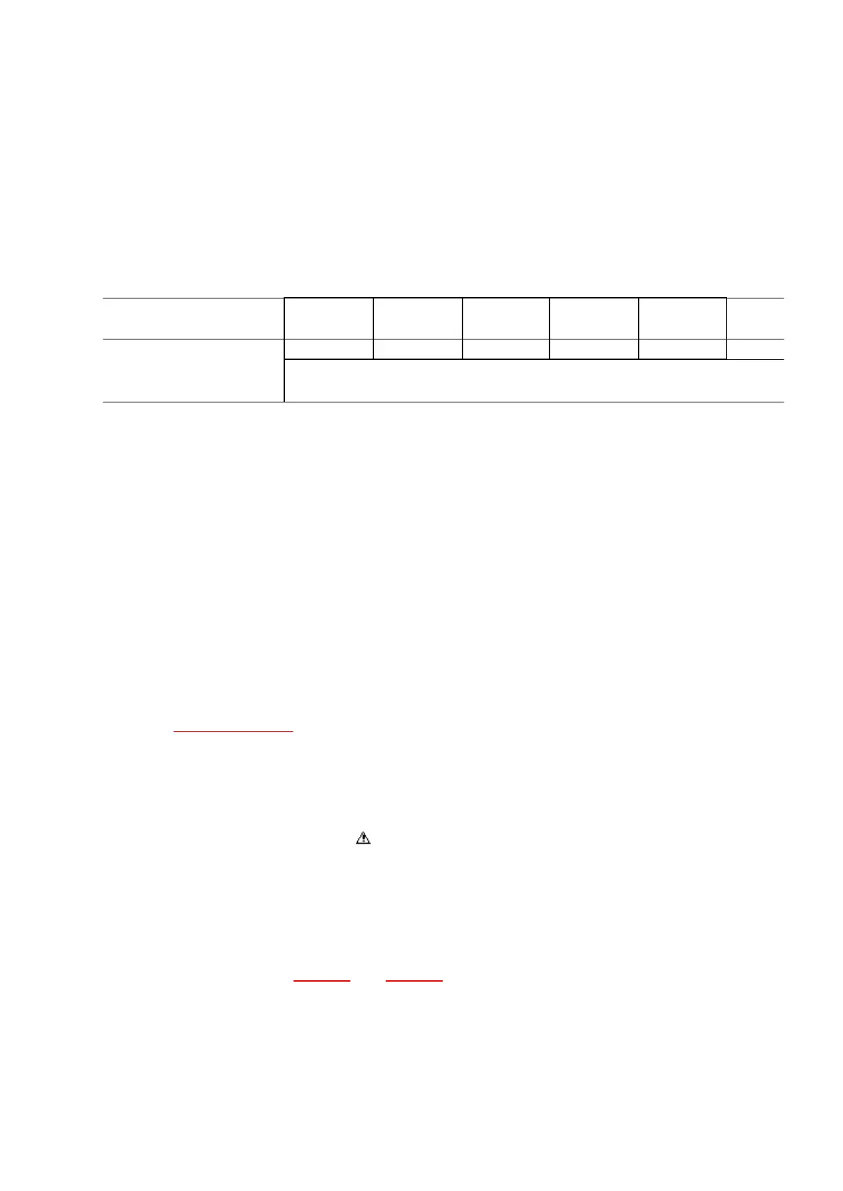
ADJUSTMENT
MEASURING
CONDITIONS
EQUIPMENT
ADJUSTMENT
P.C.B.
ADJ. POINT CONNECT
METER TO
TOUCH SENSOR
any position Oscilloscope MKB3 P.C.B. VR1 CN11-3pin 5.0V
1. Press one of the any keys hardly and check the CN11-3 pin voltage.
The voltage will increase and become steady.
2. Adjust the voltage to 5.0V with VR1 at that time.
11. Precautions before Servicing
11.1. Precautions for measuring of the output waveforms
1. The waveform was measured with a “National Digital Storage Oscilloscope VP-
5730A”. Therefore the waveforms of musical tone signals shown may differ
somewhat due to the difference in the timing of triggering.
2. Since the 1/10 test probe is used, the indicated voltage value on the bottom part of
each waveform illustration is 1/10 of the actual value (e.g. 0.2 V/cm should be 2.0 V/
cm).
3. To measure the waveforms, first set this unit to the service diagnostic mode (refer
to “WAVE ROM test ”). The WAVE ROM output will then be output as a sine wave to
facilitate the servicingcheck.
11.2. Important safety notice
- Components identified by a mark have special characteristics impotant for safety.
- When replacing any of these components, use only manufacture’s specified parts.
11.3. Symbolic Marks
The symbolic marks for resistors and capacitors which used in this circuits are
classified as following Table-1 and Table-2 .
11.3.1. RESISTORS
41
 Loading...