Network Meter Block Installation, Operation, & Maintenance Manual
Installation 9
The DIN rail mounting kit includes:
• One DIN rail mounting bracket
• Two M3 x .5 mm x 30 mm stainless steel
screws
• Two M3 x .5 mm stainless steel locknuts
To install the NMB using the DIN Rail Mounting
kit, first mount the DIN rail mounting bracket to
the NMB using the supplied screws and
locknuts. You can then mount the bracket to your
DIN rail.
3.1.2 Installing the NMB with an Instrument Housing
An NMB purchased with an instrument housing is certified for installation in Class I, Division 1, Zone 1 and
Class I, Division 2, Zone 2 hazardous locations. You also can install it in non-hazardous environments as it
has been evaluated to UL 508 – Industrial Control Equipment, a standard regarding fire and shock safety;
this standard also is used to satisfy the requirements of EU Directive 2014/35/EU regarding low voltage.
NMBs with an included instrument housing can be installed using one of the following methods:
• Mount the NMB directly to a meter using the instrument housing’s 1-inch NPT conduit hub. When
using rigid conduit systems, we highly recommend using conduit unions to later ease removing the
NMB housing from the meter fitting for servicing.
• Mount the NMB to a panel or rack using the two integral mounting feet. All ancillary conduit fittings and
cable glands must be certified according to your local electrical installation codes. Additionally, any
fittings (stopping boxes) or cable glands are required to be sealed for Division 1, Zone 1 installations.
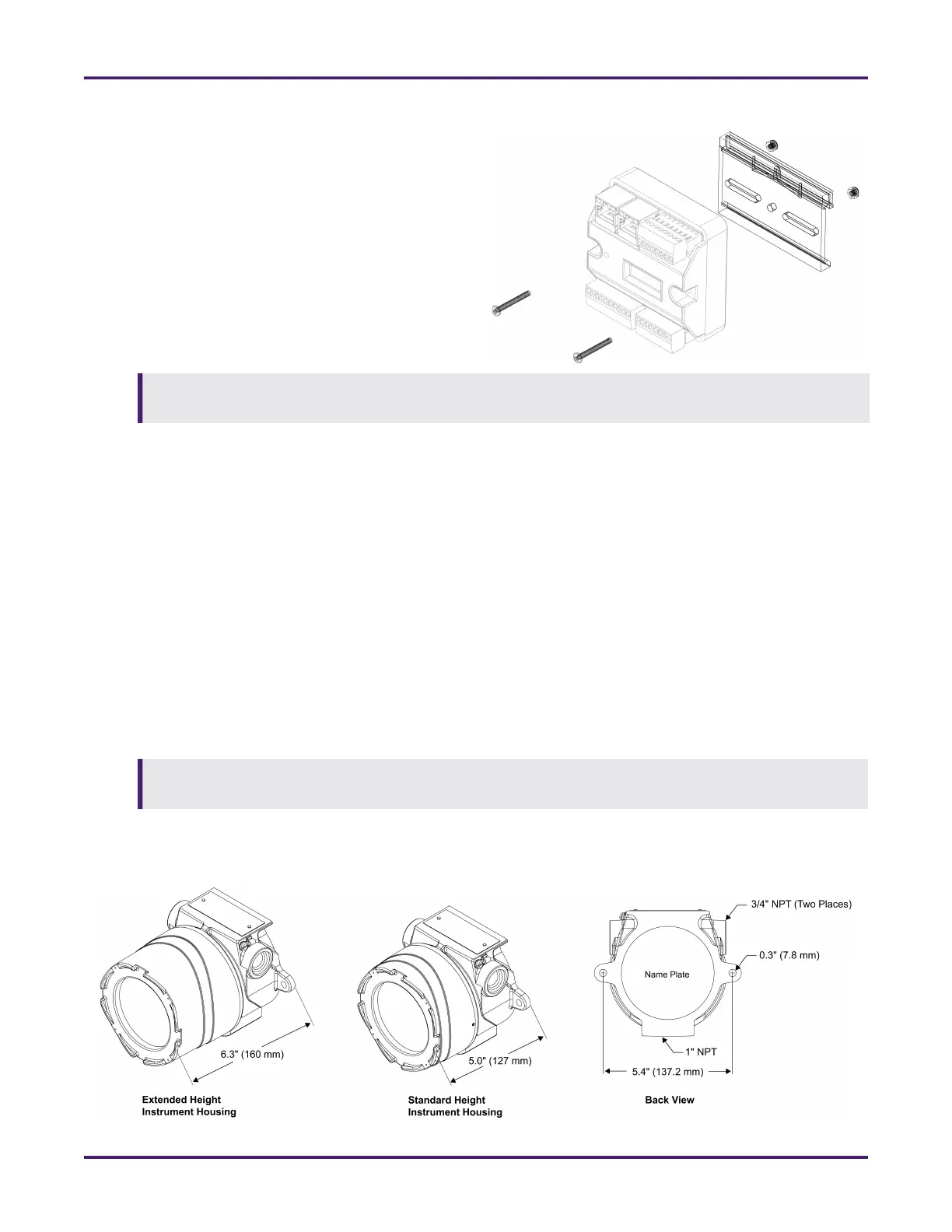
The following dimensional drawings are provided to help you plan the installation of the NMB’s instrument
housing.
This installation expects the bracket to be mounted to a standard 35 mm wide DIN rail, which is not
supplied in this kit.
It is the installers’ responsibility to ensure that all applicable local electrical safety codes and installation
practices are followed.
Figure 1: NMB with DIN Rail Mounting Kit
Figure 2: Enclosure Installation
 Loading...