Network Meter Block Installation, Operation, & Maintenance Manual
Monitoring and Configuring the NMB 31
until flow is within the turbine meter’s tolerance limits for 30 seconds plus this defined sensitivity
time.
e. In the Averaged Seconds field, type the number of seconds during which the NMB should average
pulse timing data to smooth transient conditions and avoid nuisance alarms.
f. In the Turbine Error Tolerance % field, type the percentage of allowed deviation from the meter’s
diagnostic signature before alarms are generated.
3. The Zone section contains details about the range of flow rates. In the Flow Rate Threshold row, type
the flow rate at which the turbine meter’s signature changes. For example, in the Zone 1 field, type the
flow rate threshold between zones 1 and 2; in the Zone 2 field, type the flow rate threshold between
zones 2 and 3, and so on. (The high and low flow rates that define the boundaries of each diagnostic
zone are set in the Minimum Flow Rate and Maximum Flow Rate fields in Meter > Configuration.)
The deviation values in this section represent the diagnostic signature of the turbine meter.
4. Click Apply to save your changes.
4.3.5.3 Re-Characterizing a Turbine Meter’s Signature
When a turbine meter’s signature no longer represents the meter’s behavior, such as when a rotor is
replaced or hydraulic changes are made, you can re-calculate one or more zones to update the meter’s
signature. To do so, complete the following steps:
1. Select Turbine Diagnostics > Configure.
2. In the Diagnostic Zone field, select the zones you want to reset.
3. Click Apply to perform the reset.
4. In the Diagnostic Zone field, select Auto to enable the device to calculate the new diagnostic signature.
5. Click Apply to save your changes.
4.3.6 Viewing System Status Details
The System Status tab enables you to view status information and other details about the NMB system.
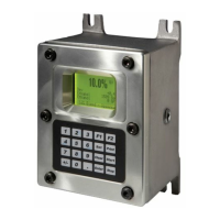
4.3.6.1 Viewing OLED Display Panel Information
To remotely view the information displayed on your NMB’s integrated display panel, such as the version
number, status, and IPv4 address, select the System Status tab > Messages menu.
4.3.6.2 Adding Custom Messages to the OLED Display Panel
You can add custom messages to your NMB’s integrated display panel. For example, you can display a
two-line message stating:
For customer support
call +1 814.898.5000.
To display custom messages on your NMB’s integrated display panel, complete the following steps:
1. Select System Status > Messages.
 Loading...