Network Meter Block Installation, Operation, & Maintenance Manual
Installation 14
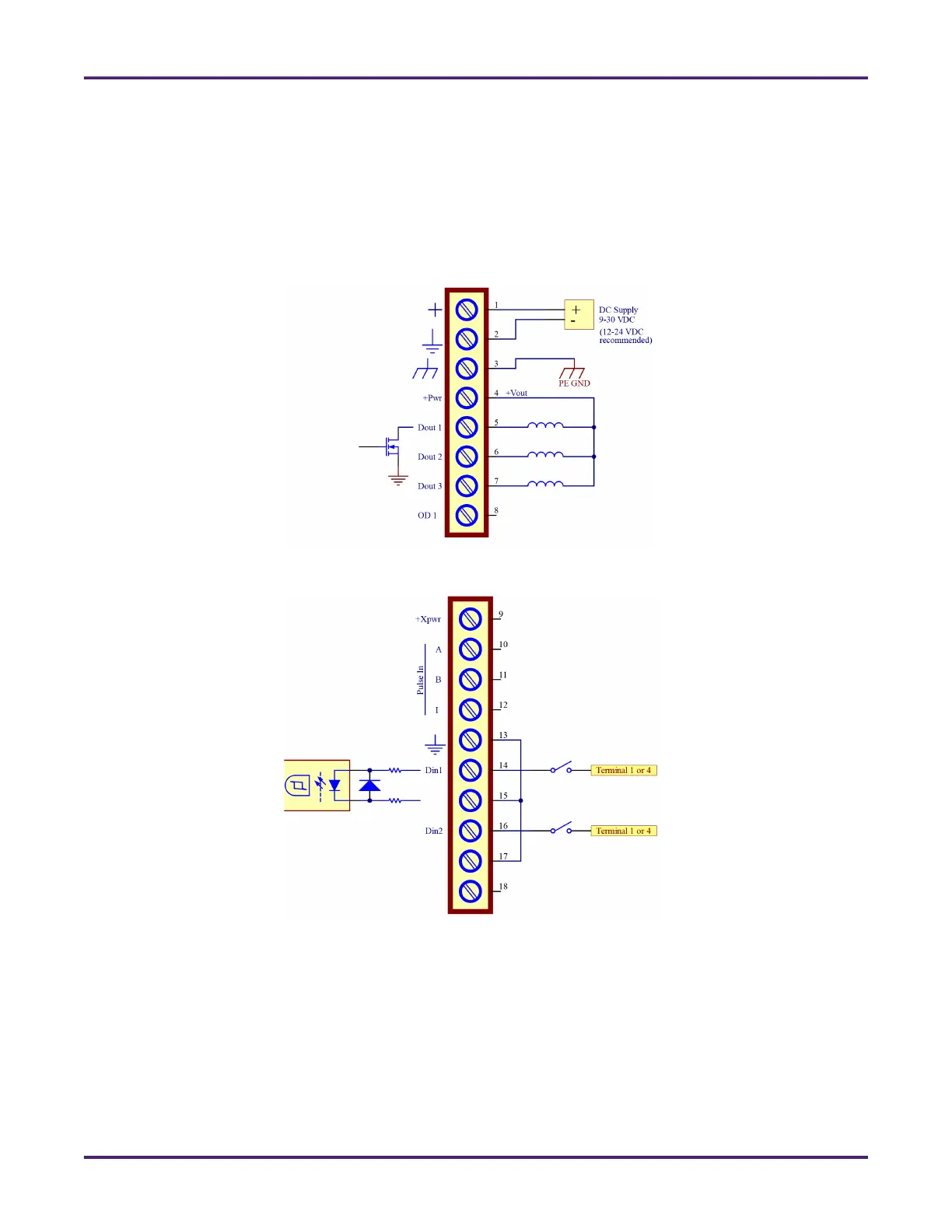
3.2.5 Typical Wiring Diagrams
All of the terminals on the NMB are labeled to ease the process of landing the wiring connections. The
following figures provide details for connecting external devices to the NMB. Callouts on the left side of the
connector in each image are the NMB internals; callouts on the right of each connector represent external
wiring/devices.
Figure 6: Power and Digital Output Connections
Figure 7: Digital Input Connections
 Loading...