Network Meter Block Installation, Operation, & Maintenance Manual
Installation 17
3.3 Finishing and Testing the Installation
3.3.1 Power Supply
The NMB requires a power source capable of providing 12 to 24 VDC
and approximately 150 mA maximum load (not including any external DC
load).
The first time you activate the NMB’s power supply, the red LED light
should begin blinking and the integrated display panel should provide
details about the NMB.
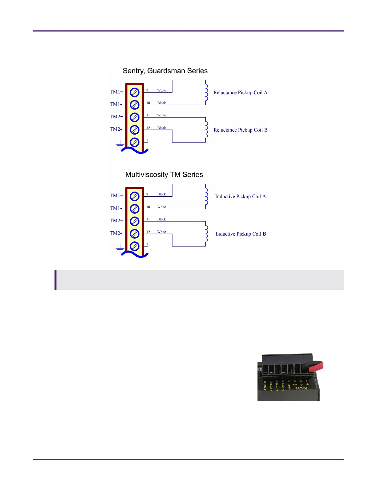
The NMT contains a preamplifier not found in the NMB for low-voltage inputs. If pulse transmission to a
SCADA system or flow computer is required for the application, the addition of a PA-6 is recommended.
Figure 12: Wiring the NMT Directly to Pickup Coils in Sentry,
Guardsman, and MV Turbine Meters
Figure 13: Power Supply Inputs
 Loading...