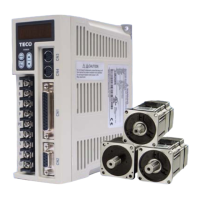
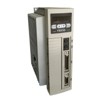
5-31
Two types of pulse command can be connected, (Open collector) and (Line driver).
Please refer to section 2-2-1 for the pulse wiring method.
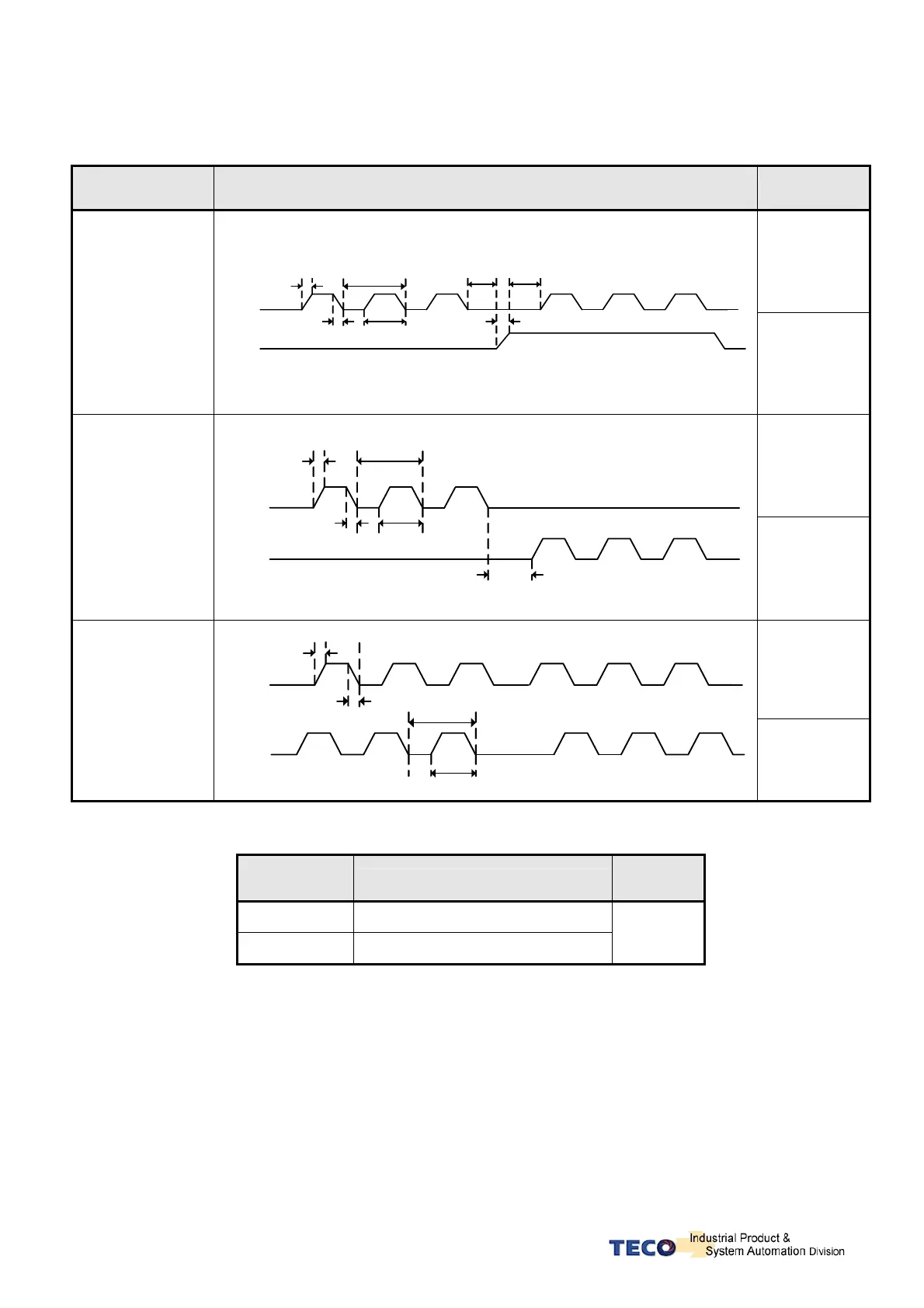
Pulse command timing should be in accordance with the time sequence standard below.
Pulse Command
Types
Time Sequence Diagram of Pulse Command Time Standard
Line Driver:
t1, t2 ≦ 0.1μs
t3 > 3μs
τ ≧ 1.0μs
(τ/T) ≦ 50%
(Pulse)+
(Sign)
t3 t3
t2
t1
T
t
t2
Pulse
Sign
OpenCollector:
t1, t2 ≦ 0.2μs
t3 > 3μs
τ ≧ 2.0μs
(τ/T) ≦ 50%
LineDrive:
t1, t2 ≦ 0.1μs
t3 > 3μs
τ ≧ 1.0μs
(τ/T) ≦ 50%
(CCW)/
(CW) Pulse
t1
t2
T
t
t3
Pulse
Sign
OpenCollector:
t1, t2 ≦ 0.2μs
t3 > 3μs
τ ≧ 2.0μs
(τ/T) ≦ 50%
LineDrive:
t1, t2 ≦ 0.1μs
τ ≧ 1.0μs
(τ/T) ≦ 50%
AB-Phase Pulse
t2
t1
T
t
Pulse
Sign
OpenCollector:
t1, t2 ≦ 0.2μs
τ ≧ 2.0μs
(τ/T) ≦ 50%
Position command can be disabled ( Inhibited) by extrernal input contact INH.
Input Contact
INH
Description
Control
Mode
0 Position Pulse command enabled
1 Position Pulse command disabled
Pe
Note: Input contacts status “1” (ON) and “0” (OFF)
Please check section 5-6-1 to set the required high /Low signal levels ( PNP/NPN) selection.
 Loading...