2-31
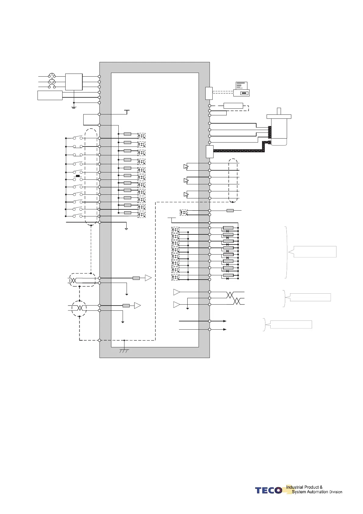
2-3-5 Torque Control Mode (T Mode)
U
1
R1
R1
R1
R1
R1
R1
R1
R1
4
5
9
12
2
8
10
48
DI-4
DI-5
IG24
(SON)
(CCWL)
(CWL)
(EMC)
(MDC)
(ALRS)
(S PD1)
TIC
AG
SIC
AG
FG
C
N
4
PC
RS232
PC
P1
P
V
W
FG
SERVO
MOTOR
C
N
2
35
36
37
38
39
40
43
44
Z0
DOCOM
*2
R4
+Vc
18
19
20
21
22
23
24
25
DC24V
45
44
LOAD
LOAD
LOAD
LOAD
LOAD
LOAD
LOAD
LOAD
DOCOM
*1
30
31
32
MON1
AG
MON2
33
34
+15V
-15V
50
SERVO
R1
11
(SPD2)
R2
26
29
R2
27
29
20K
Ω
20K
Ω
Speed Limit Input(±10V)
NFB
DC 24V
R
S
T
r, 24V
s, 0V
R
S
T
FG
47
45
DI-1
DI-9
DI-12
DI-2
DI-8
DI-11
DO-1
DO-3
DO-4
DO-5
DO-6
DO-7
DO-8
PA
/PA
PB
/PB
PZ
/PZ
IP24
DICOM
Supply
Filter
Internal +24V DC
Digital input common
Servo ON
CCW Limit
CW Limit
Emergency stop
Model Control
Alarm Clear
Torque Inverse(TRQINV)
Speed 1
Speed 2
+24V ground
Torque Command(0~10V)
Analog Ground
Analog Ground
Shield ground
Regeneration resistor
Encoder
Encoder Output A Phase
Encoder Output/A Phase
Encoder Output B Phase
Encoder Output Z Phase
External supply
*Max Vc=24V
Vc=2 4V , R4=4.7 K
Ω
Vc=12V , R4=2.4KΩ
Vc=5V , R4=1.0K
Ω
Servo Ready(RDY)
Alam(ALM)
Zero Speed(ZS)
In Speed(INS)
Limiting Torque/Alarm Code 0
P in Action/Alarm Code 1
Servo in limit/ Alarm Code 2
Base Block /Alarm Code 3
Max Voltage: 24V
Max Output Current :10mA
Analog Monitor Output 1
Analog Grounding
Analog Monitor Output 2
Max Output Current 5mA
+15V PW output (AG)
-15
V PW
output
(AG)
Max Output Current 10mA
R1
R1
6
7
DI-
10
DI-6
DI-7
Torque CW Selecting (RS1)
Torque CCW Selecting (RS2)
Control Power
Supply
DO-2
Encoder Output /B Phase
Encoder Output /Z Phase
Notes: 1. Pe mode =External pulse positioning command
2. DOCOM means common port of digital input
(DOCOM must connect to IG24 when using internal power supply)
 Loading...