5-43
5-4-5 Definition of Direction
In position mode, user can use Pn314 (Position Command Direction Definition) to define motor rotation
direction. The setting is showed as follow:
Parameter
Signal
Name Setting Description
Control
Mode
0 Clockwise (CW)
★
Pn314
Definition of position
command direction (from
motor load end)
CCW
CW
1 Counter Clockwise (CCW)
Pi
Pe
New setting will become effective after re-cycling the power.
5-4-6 Gain Adjustment
The table below shows the parameters for adjusting the position loop.
Two position loop gains can be selected from input contact terminals according to table below.
For selection methods refer to section. 5-3-11.
Parameter
Signal
Name Default Unit Setting Range
Control
Mode
Pn310 Position Loop Gain1 40 1/s 1~1000 Pe/Pi
Pn311 Position Loop Gain 2 40 1/s 1~1000 Pe/Pi
Pn312 Position Feed-Forward Gain 0 % 0~100 Pe/Pi
Cn033
Speed Feed-Forward Smooth Filter
500 Hz 0~1000 Pe/Pi
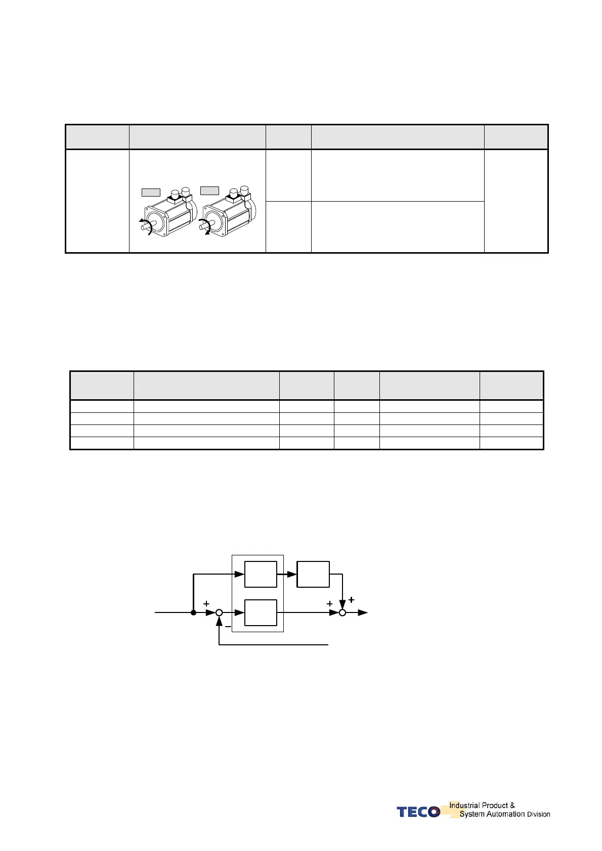
Diagram below shows the position controller. Adjust a higher gain value can reduse response time.
Position Feed-Forward Gain can also be used to shorten the positioning time.
Refer to section 5-5 for Position Loop Gain Adjustment methods.
Position Controllor
Position Pulse
Command
Encoder Pulse Feed Back
p
K
pff
K
:K
:K
pff
p
Position Loop Gain (1/s)
Filter
Position Loop
Feed-Forward Gain (%)
 Loading...