Operating Inform atio n—2205 Service
CONTROLS, CONNECTORS, AND INDICATORS
The following descriptions are intended to fa
miliarize the operator with the location and function
of the instrument’s controls, connectors, and
indicators.
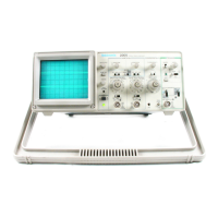
Refer to Figure 2-2 for the location of items 1
through 28.
POWER AND DISPLAY
0 INTENSITY Control—Adjusts the brightness of
all displayed waveforms.
(F ) BEAM FIND Button—Compresses the vertical
f and horizontal deflection to within the graticule
I area and intensifies the display to aid the user
f in locating traces that are overscanned or
deflected outside of the crt viewing area.
( I}) f FOCUS Control—Adjusts for optimum display
J definition. Once set, proper focusing is
maintained over a wide range of display
: intensity.
0 TRACE ROTATION C ontrol-P erm its aiign-
ment of the trace with the horizontal graticule
line. This control is a screwdriver adjustment
that, once set, should require little attention
during normal operation.
(b ) POWER Switch—Turns instrument power on
V or off-
(j3 ) Power On Indicator—Lights up while instru-
ment is operating.
VERTICAL
(7) Channel 1 Vertical POSITION C o n tro l-
Controls the vertical display position of the
Channel 1 signal. In X-Y mode the control is
inactive.
0 Channel 2 Vertical POSITION C o ntrol-
Controls the vertical display position of the
Channel 2 signal. In X-Y mode the control
vertically positions the display.
@ MODE Switch CH 1 -BOTH-CH 2-S elects
either a single channel fo r display or the dual-
channel display mode.
CH 1—Selects only the Channel 1 input sig
nal for display.
BOTH—Selects a combination of Channel 1
and Channel 2 input signals for display. The
CH 1-BOTH-CH 2 switch must be in the
BOTH position for ADD, ALT, and CHOP
operation.
CH 2—Selects only the Channel 2 input sig
nal for display.
@ MODE Switch NORM-CH 2 INVERT-Inverts
the Channel 2 display when in the CH 2
INVERT position. With CH 2 inverted, the oscil
loscope may be operated as a differential am
plifier when the BOTH-ADD vertical mode is
selected. For noninverting Channel 2 display,
select NORM position.
( t j) MODE Switch ADD-ALT-CHOP-Sets ! the
dual-channel vertical display mode.
ADD—Displays the sum of Channel 1 and
Channel 2 input signals when BOTH is also
selected. The difference of the Channel 1
and Channel 2 input signals is displayed
: when the Channel 2 signal is inverted.
ALT—Alternately displays the Channel 1 and
Channel 2 input signals. The alternation
occurs during retrace at the end of each
sweep. ALT vertical mode is most useful for
viewing both channel input signals at sweep
rates of 0.5 ms per division and faster.
CHOP—Switches the display between the
Channel 1 and Channel 2 vertical input
signals during the sweep. The chopped
switching rate (CHOP frequency) is
approximately 500 kHz.
(12) CH 1 and CH 2 VOLTS/DIV Sw itches-Seleet
the vertical channel deflection factors from
5 mV to 5 V per division in a 1-2 -5 sequence.
IX —Front-panel marking that indicates the
deflection factor set by the VOLTS/DIV
switch when a signal adapter, IX probe, or
a coaxial cable is attached to the channel
input connector.
10X PROBE—Front-panel marking that indi
cates the deflection factor set by the
VOLTS/DIV switch when a 10X probe is
attached to the channel input connector.
2-3

 Loading...