Performance Check Procedure—2205 Service
TRIGGER
Equipment Required (See Table 4-1):
Leveled Sine-Wave Generator (item 2)
Dual-Input Coupler (Itehrt T)
50-D Coaxial Cable (Item 6)
50-n Termination (Item 8)
INITIAL CONTROL SETTINGS
Vertical
POSITION (both)
MODE
Midrange
CH 1, NORM
CH 1 VOLTS/DIV
0.1 V
CH 2 VOLTS/DIV 1 V
VOLTS/DIV Variable (both)
CAL detent
AC-GND-DC (both)
DC
Horizontal
POSITION (COARSE and FINE) Midrange
MAG XI
SEC/DIV 0.2 ms
SEC/DIV Variable CAL detent
■Trigger-1-1'"'''''''''';'1"'
SLOPE Positive <-/-)
LEVEL Midrange
- MODE ' ' ■ P-P AUTO
SOURCE VERT MODE
PROCEDURE STEPS
1. Check Internal Triggering
a. Connect the leveled sine-wave generator out
put via a 50-n coaxial cable and a 50-n termination
to the CH 1 o r X input connector.
b. Set the generator to produce a 3-division
display at an output frequency of 5 MHz.
c. Set channel 1 VOLTS/DIV switch to 1 V.
combination given in Table 4-4. Ensure that the
TRIG'D light comes on when triggered.
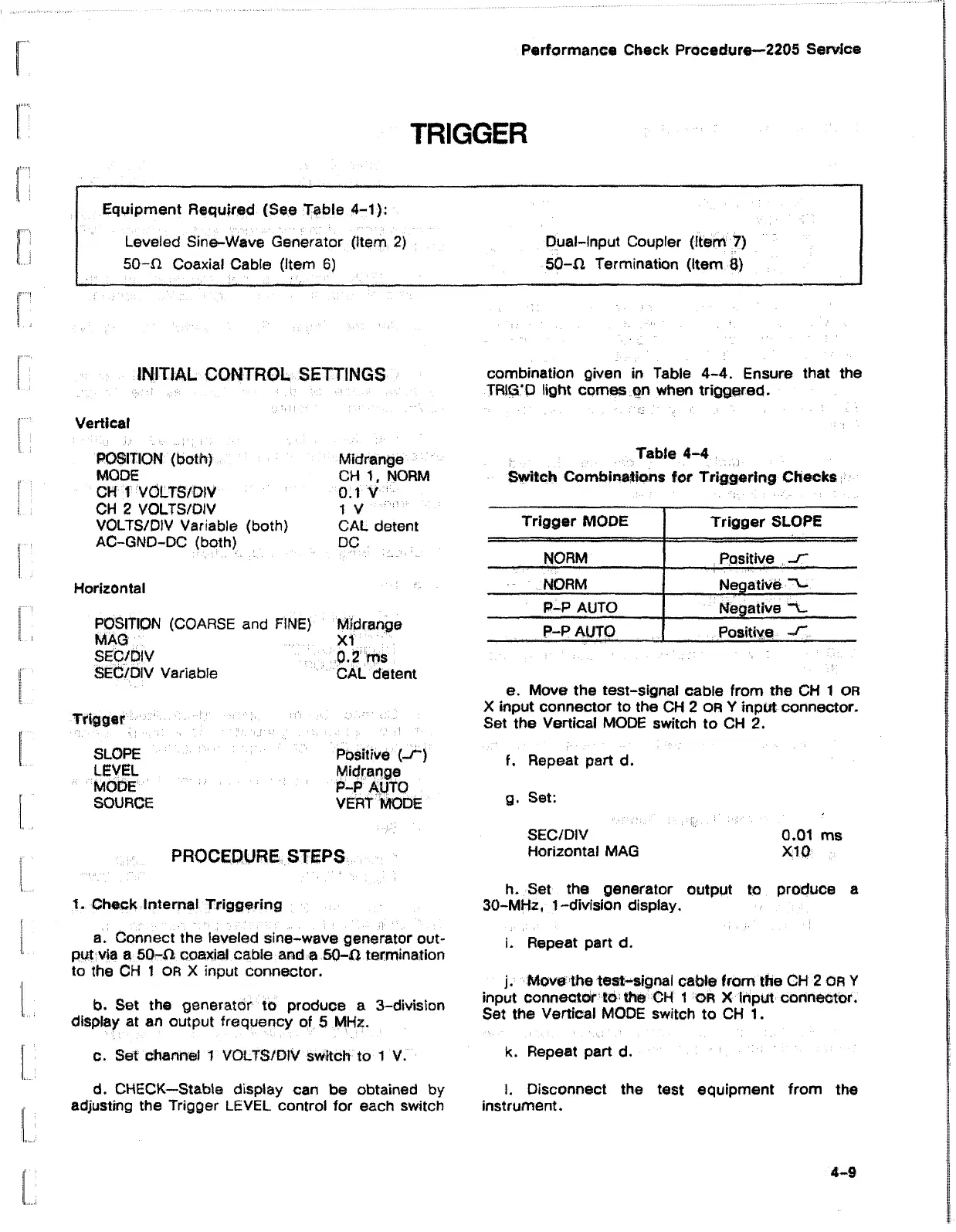
Table 4-4
Switch Combinations for Triggering Checks
Trigger MODE
Trigger SLOPE
NORM
Positive -T
NORM
Negative “V.
P-P AUTO
Negative “V.
P-P AUTO
Positive
e. Move the test-signal cable from the CH 1 OR
X input connector to the CH 2 OR Y input connector.
Set the Vertical MODE switch to CH 2.
f. Repeat part d.
g. Set:
SEC/DIV 0.01 ms
Horizontal MAG X10
h. Set the generator output to produce a
30-MHz, 1 -division display.
i. Repeat part d.
j. Move the test-signal cable from the CH 2 or Y
input connector to the CH 1 or X Input connector.
Set the Vertical MODE switch to CH 1.
k. Repeat part d.
d. CHECK—Stable display can be obtained by 1. Disconnect the test equipment from the
adjusting the Trigger LEVEL control for each switch instrument.
4-8

 Loading...


