Adjustment Procedure—2205 Service
d. Set the CH 1 VOLTS/DIV switch to 1 V.
e. ADJUST—Trig Sensitivity (R489) while rotating
the Trigger LEVEL control slowly so that the trigger is
just able to be maintained.
f. CHECK—The TRiG’D/READY LED is on when
triggered.
3. Adjust Slope Balance (R481)
a. Set the CH 1 VOLTS/DIV switch to 50 mV.
b. Set the generator to produce a 4-division
display.
c. ADJUST—Slope Bal (R481) for a downward
vertical shift of 0.22-division at the start of the
sweep when changing the Trigger SLOPE switch
between the positive (_/-) and negative (~\_)
positions.
4. Adjust Auto Level (R445 and R446)
a. Set:
Trigger SLOPE Positive (~r)
Trigger LEVEL Fully clockwise
b. Set the generator to produce a 5-division
display.
c. Set the CH 1 VOLTS/DIV switch to 0.5 V.
d. ADJUST—(+) Auto Level (R446) so that the
vertical display just solidly triggers on the positive
peak of the signal.
e. Set:
Trigger SLOPE Negative ("V.)
Trigger LEVEL Fully
counter-
clockwise
■bi Set the generator to produce a 5-MHz,
3-division display.
c. Set the GH 1 VOLTS/DIV switch to 50 mV.
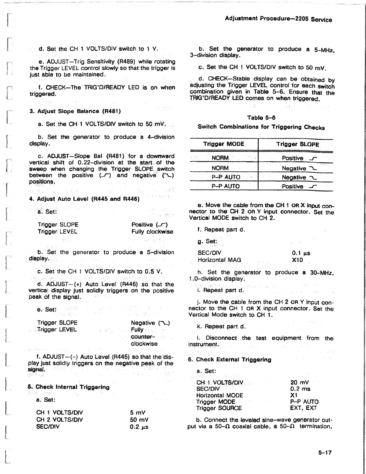
d. CHECK—Stable display can be obtained by
adjusting the Trigger LEVEL control for each switch
combination given in Table 5-6. Ensure that the
TRIG’D/READY LED comes on when triggered.
Table 5-6
Switch Combinations for Triggering Checks
Trigger MODE
Trigger SLOPE
NORM
Positive ~ r
NORM
Negative ~v_
P-P AUTO
Negative *\_
P-P AUTO
Positive -J~
e. Move the cable from the CH 1 o r X input con
nector to the CH 2 OR Y input connector. Set the
Vertical MODE switch to CH 2.
f. Repeat part d.
g. Set:
SEC/DIV 0.1 ps
Horizontal MAG X10
h. Set the generator to produce a 30-MHz,
1.0-division display.
i. Repeat part d.
j. Move the cable from the CH 2 o r Y input con
nector to the CH 1 o r X input connector. Set the
Vertical Mode switch to CH 1.
k. Repeat part d.
i. Disconnect the test equipment from the
instrument.
f. ADJUST-(-) Auto Level (R445) so that the dis
play just solidly triggers on the negative peak of the
5. Check Internal Triggering
a. Set:
CH 1 VOLTS/DIV
CH 2 VOLTS/DIV
SEC/DIV
5 mV
50 mV
0.2 ps
6. Check External Triggering
a. Set:
CH 1 VOLTS/DIV
SEC/DIV
Horizontal MODE
Trigger MODE
Trigger SOURCE
20 mV
0.2 ms
XI
P-P AUTO
EXT, EXT
b. Connect the leveled sine-wave generator out
put via a 50-0 coaxial cable, a 50-0 termination,
5-17

 Loading...


