Theory of Operation—2205 Service
DETAILED CIRCUIT DESCRIPTION
VERTICAL
Attenuators
The Channel 1 and Channel 2 Attenuator circuits,
shown on Diagram 1, are identical except for the ad
ditional Invert circuitry in the Channel 2 Paraphase
Amplifier. Therefore, only the Channel 1 Attenuator
is described, with the Invert circuitry of Channel 2
discussed separately.
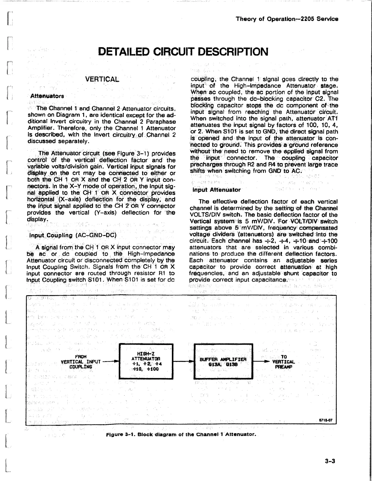
The Attenuator circuit (see Figure 3-1) provides
control of the vertical deflection factor and the
variable volts/division gain. Vertical input signals for
display on the crt may be connected to either or
both the CH 1 OR X and the CH 2 OR Y input con
nectors. In the X-Y mode of operation, the input sig
nal applied to the CH 1 OR X connector provides
horizontal (X-axis) deflection for the display, and
the input signal applied to the CH 2 OR Y connector
provides the vertical (Y-axis) deflection for the
display.
Input Coupling (ACTfiND-pti)
A signal from the CH 1 OR X input connector may
be ac or dc coupled to the High-Impedance
Attenuator circuit or disconnected completely by the
Input Coupling Switch. Signals from the CH 1
OR X
input connector are routed through resistor R1 to
Input Coupling switch SI 01. When SI 01 is set for dc
coupling, the Channel 1 signal goes directly to the
input of the High-Impedance Attenuator stage.
When ac coupled, the ac portion of the Input signal
passes through the dc-blocking capacitor C2. The
blocking capacitor stops the dc component of the
input signal from reaching the Attenuator circuit.
When switched into the signal path, attenuator ATI
attenuates the input signal by factors of 100, 10, 4,
or 2. When S101 is set to GND, the direct signal path
is opened and the input of the attenuator is con
nected to ground. This provides a ground reference
without the need to remove the applied signal from
the input connector. The coupling capacitor
precharges through R2 and R4 to prevent large trace
shifts when switching from GND to AC.
Input Attenuator
The effective deflection factor of each vertical
channel is determined by the setting of the Channel
VOLTS/DiV switch. The basic deflection factor of the
Vertical system is 5 mV/DIV. For VOLT/OiV switch
settings above 5 mV/DIV, frequency compensated
voltage dividers (attenuators) are switched into the
circuit. Each channel has —2, —4, -f-10 and -*-100
attenuators that are selected in various combi
nations to produce the different deflection factors.
Each attenuator contains an adjustable series
capacitor to provide correct attenuation at high
frequencies, and an adjustable shunt capacitor to
provide correct input capacitance.
figure 3-1. Block diagram of the Channel 1 Attenuator.
3-3

 Loading...


