Performance Check Procedure—2205 Service
i. CHECK—Timing accuracy is within 4% (0.32
division at the tenth vertical graticule line), and
linearity is within 7% (0.14 division over any 2 of the
center 8 divisions). Exclude any portion of the
sweep past the 50th magnified division.
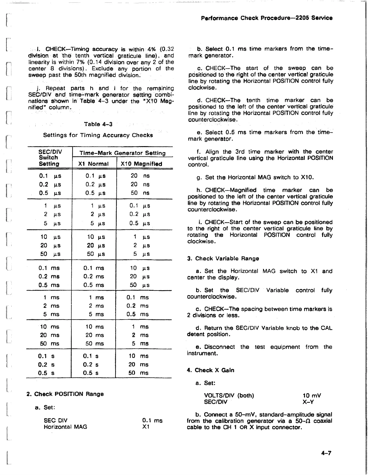
j. Repeat parts h and i for the remaining
SEC/DIV and time-mark generator setting combi
nations shown in Table 4-3 under the “X10 Mag
nified” column.
Table 4-3
Settings for Timing Accuracy Checks
SEC/DIV
Switch
Setting
Time-Mark Generator Setting
XI Normal
X10 Magnified
0.1 jxs 0.1 jxs
20 ns
0.2 p.s
0.2 ns 20 ns
0.5 p.s
0.5 ns
50 ns
1 J1S
1 ns 0.1 ns
2 ns
2 ns
0.2 ns
5 jxs
5 ns
0.5 ns
10 jis
10 ns i ns
20 fxs
20 ns
2 ns
50 ns so ns
5 ns
0.1 ms 0.1 ms
10 ns
0.2 ms
0.2 ms
20 ns
0.5 ms
0.5 ms 50 ns
1 ms 1 ms
0.1 ms
2 ms
2 ms
0.2 ms
5 ms 5 ms
0.5 ms
10 ms 10 ms
1 ms
20 ms 20 ms
2 ms
50 ms
50 ms
5 ms
0.1 s
0.1 s
10 ms
0.2 s
0.2 s 20 ms
0.5 s
0.5 s
50 ms
2. Check POSITION Range
a. Set:
SEC DIV 0.1 ms
Horizontal MAG XI
b. Select 0.1 ms time markers from the time-
mark generator.
c. CHECK—The start of the sweep can be
positioned to the right of the center vertical graticule
line by rotating the Horizontal POSITION control fully
clockwise.
d. CHECK—The tenth time marker can be
positioned to the left of the center vertical graticule
line by rotating the Horizontal POSITION control fully
counterclockwise.
e. Select 0.5 ms time markers from the time-
mark generator.
f. Align the 3rd time marker with the center
vertical graticule line using the Horizontal POSITION
control.
g. Set the Horizontal MAG switch to X I0.
h. CHECK—Magnified time marker can be
positioned to the left of the center vertical graticule
line by rotating the Horizontal POSITION control fully
counterclockwise.
i. CHECK—Start of the sweep can be positioned
to the right of the center vertical graticule line by
rotating the Horizontal POSITION control fully
clockwise.
3. Check Variable Range
a. Set the Horizontal MAG switch to XI and
center the display.
b. Set the SEC/DIV Variable control fully
counterclockwise.
c. CHECK—The spacing between time markers is
2 divisions or less.
d. Return the SEC/DIV Variable knob to the CAL
detent position.
e. Disconnect the test equipment from the
instrument.
4. Check X Gain
a. Set:
VOLTS/DIV (both) 10 mV
SEC/DIV X-Y
b. Connect a 50-mV, standard-amplitude signal
from the calibration generator via a 50-fl coaxial
cable to the CH 1 OR X input connector.
4-7

 Loading...


