Maintenance—2205 Service
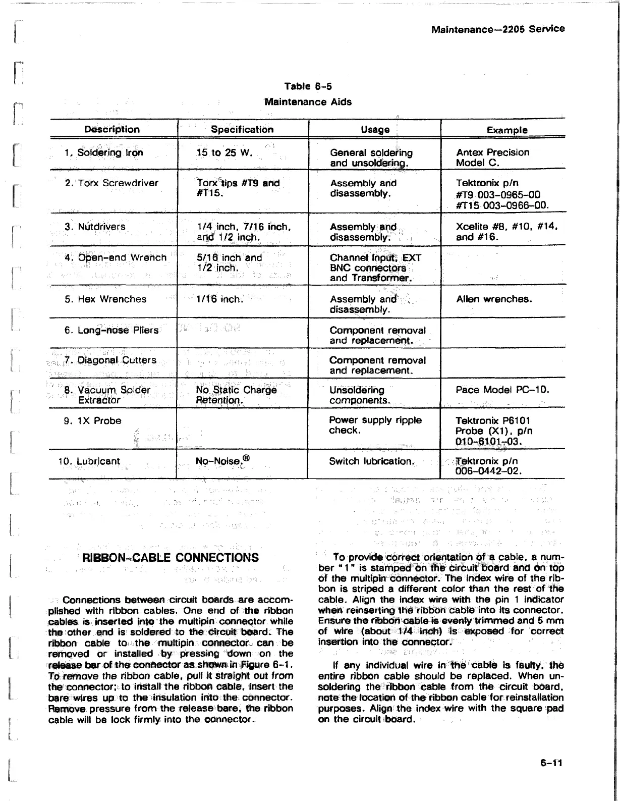
Table 6-5
Maintenance Aids
Description
Specification
Usage
Example
1. Soldering Iron
15 to 25 W.
General soldering
and unsoldering.
Antex Precision
Model C.
2. Torx Screwdriver
Torx tips #T9 and
# fis .
Assembly and
disassembly.
Tektronix p/n
#T9 003-0965-00
#T15 003-0966-00.
3. Nutdrivers 1/4 inch, 7/16 inch,
and 1/2 inch.
Assembly and
disassembly.
Xcelite #8, #10, #14,
and #16.
4 Open-end Wrench
5/16 inch and
1/2 inch.
Channel Input, EXT
BNC connectors
and Transformer.
5. Hex Wrenches
1/16 inch. Assembly and
disassembly.
Allen wrenches.
6. Long-nose Pliers
Component removal
and replacement.
7. Diagonal Cutters
Component removal
and replacement.
8. Vacuum Solder
Extractor
No Static Charge
Retention.
Unsoldering
components.
Pace Model PC-10.
9. IX Probe
Power supply ripple
check.
Tektronix P6101
Probe (XI). p/n
010-6101-03.
10. Lubricant
No-Noise,® Switch lubrication.
Tektronix p/n
006-0442-02.
RIBBON-CABLE CONNECTIONS
Connections between circuit boards are accom
plished with ribbon cables. One end of the ribbon
cables is inserted into the multipin connector while
the other end is soldered to the circuit board. The
ribbon cable to the multipin connector can be
removed or installed by pressing down on the
release bar of the cwhector as shown in Figure 6-1.
To remove the ribbon cable, pull it straight out from
the connector; to install the ribbon cable, insert the
bare wires up to the insulation into the connector.
Remove pressure from the release bare, the ribbon
cable will be lock firmly into the connector.
To provide correct orientation of a cable, a num
ber "1" is stamped on the circuit board and on top
of the multipin connector. The index wire of the rib
bon is striped a different color than the rest of the
cable. Align the index wire with the pin 1 indicator
when reinserting the ribbon cable into its connector.
Ensure the ribbon cable is evenly trimmed and 5 mm
of wire (about 1/4 inch) is exposed for correct
insertion into the connector.
If any individual wire in the cable is faulty, the
entire ribbon cable should be replaced. When un
soldering the ribbon cable from the circuit board,
note the location of the ribbon cable for reinstallation
purposes. Align the index wire with the square pad
on the circuit board.
6-11

 Loading...


