Adjustment Procedure—2205 Service
g. Return the CH 1 VOLTS/DIV Variable control to
the CAL detent
3. Adjust Channel 2 Invert Balance (R84)
a. Position the trace on the center horizontal
graticule line using the Channel 2 POSITION control.
b. Set Vertical MODE switch to CH 2 INVERT.
c. ADJUST—CH 2 Invert Bal (R84) to set the trace
to the center horizontal graticule line.
d. Set Vertical MODE switch to NORM.
rotate the CH 1 VOLTS/DIV Variable control fully
counterclockwise and CHECK that the display
decreases to two divisions or less. Then return the
CH 1 VOLTS/DIV Variable control to the CAL detent
and continue with the 50-mV check.
b. Move the cable from the CH 1 OR X input con
nector to the CH 2 OR Y input connector. Set the
Vertical MODE switch to CH 2.
c. Repeat part b using the Channel 2 controls.
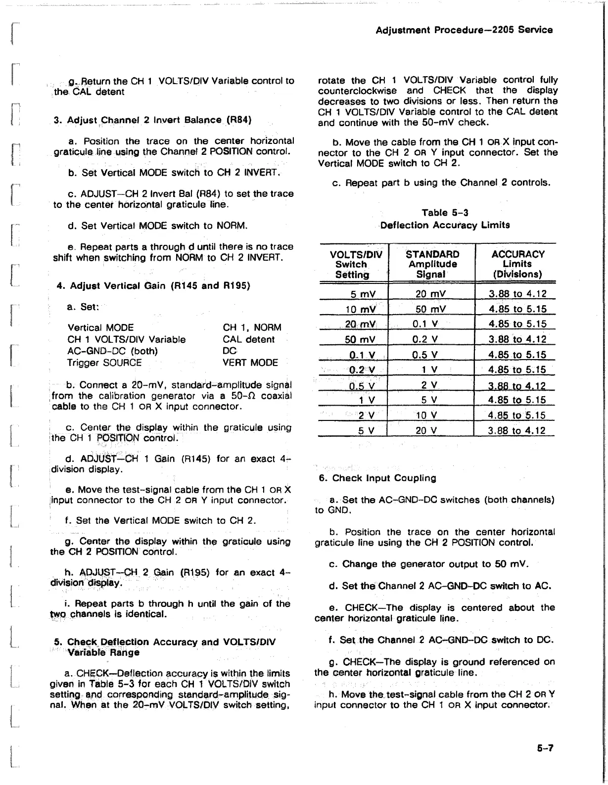
Table 5-3
Deflection Accuracy Limits
e. Repeat parts a through d until there is no trace
shift when switching from NORM to CH 2 INVERT.
4. Adjust Vertical Gain (R145 and R195)
a. Set:
Vertical MODE
CH 1 VOLTS/DIV Variable
AC-GND-DC (both)
Trigger SOURCE
CH 1, NORM
CAL detent
DC
VERT MODE
b. Connect a 20-mV, standard-amplitude signal
from the calibration generator via a 50-D coaxial
cable to the CH 1 or X input connector.
c. Center the display within the graticule using
the CH 1 POSITION control.
d. ADJUST-CH 1 Gain (R145) for an exact 4-
division display.
e. Move the test-signal cable from the CHI or X
input connector to the CH 2 OR Y input connector.
f. Set the Vertical MODE switch to CH 2.
g. Center the display within the graticule using
the CH 2 POSITION control.
h. ADJUST-CH 2 Gain (R195) for an exact 4-
division display.
VOLTS/DIV
STANDARD
ACCURACY
Switch
Amplitude
Limits
Setting
Signal (Divisions)
5 mV
20 mV 3.88 to 4.12
10 mV
50 mV
4.85 to 5.15
20 mV
0.1 V 4.85 to 5.15
50 mV
0.2 V 3.88 to 4.12
0.1 V
0.5 V
4.85 to 5.15
0.2 V
1 V
4.85 to 5.15
...
0.5 V
..
2 V
3.88 to 4.12
1 V
5 V
4.85 to 5.15
2 V 10 V 4.85 to 5.15
5 V 20 V 3,88 to 4.12
6. Check Input Coupling
a. Set the AC-GND-DC switches (both channels)
to GND.
b. Position the trace on the center horizontal
graticule line using the CH 2 POSITION control.
c. Change the generator output to 50 mV.
d. Set the Channel 2 AC-GND-DC switch to AC.
i. Repeat parts b through h until the gain of the
two channels is identical.
e. CHECK—The display is centered about the
center horizontal graticule line.
5. Check Deflection Accuracy and VOLTS/DIV
Variable Range
a. CHECK—Deflection accuracy is within the limits
given in Table 5-3 for each CH 1 VOLTS/DIV switch
setting and corresponding standard-amplitude sig
nal. When at the 20-mV VOLTS/DIV switch setting,
f. Set the Channel 2 AC-GND-DC switch to DC.
g. CHECK—The display is ground referenced on
the center horizontal graticule line.
h. Move the test-signal cable from the CH 2 OR Y
input connector to the CH 1 OR X input connector,
5-7

 Loading...


