Operating Information—2205 Service
GH 2—Trigger signal is obtained from the
CH 2 DR Y input. The CH 2 INVERT switch
also inverts the polarity of the internal
Channel 2 trigger signal when the Channel 2
display is inverted.
EXT—Selects external trigger source. The
actual form these triggers take is selected
by the second SOURCE switch.
LINE—Routes a sample of the ac-pow er-
line signal to the trigger circuit.
EXTMO—Divides the external signal applied
to the EXT INPUT or Z connector by a
factor of ten before applying it to the trigger
circuit.
EXT—Routes an external signal applied to
the EXT INPUT or Z connector to the trigger
circuit.
EXT=Z—Routes the signal applied to the
EXT INPUT OR Z connector to the Z-Axis
amplifier rather than the trigger circuit.
28) EXT INPUT OR Z Connector—Provides for
connection of external signals either to the
trigger circuit for external triggering or to the
Zr*Axis amplifier for intensity modulation of the
crt display.
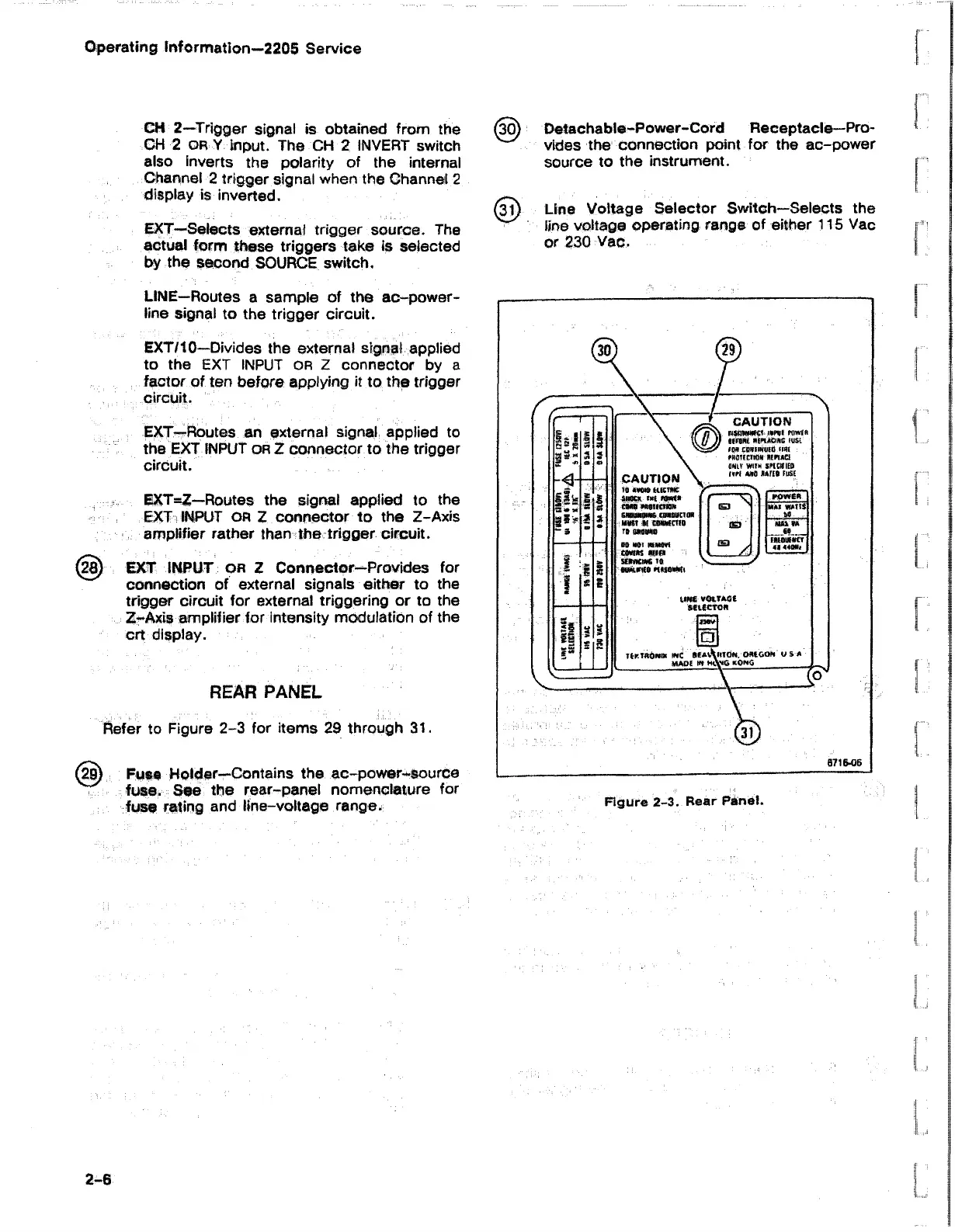
REAR PANEL
Refer to Figure 2-3 for items 29 through 31.
(29) Fuse Holder—Contains the ac-pow er-source
fuse. See the rear-panel nomenclature for
fuse rating and line-voltage range.
(30) Detachable-Power-Cord Receptacle—Pro-
v- '/ vldes the connection point for the ac-power
source to the instrument.
(3t) Line Voltage Selector Switch—Selects the
line voltage operating range of either 115 Vac
or 230 Vac.

 Loading...


