Performance Check Procedure—2205 Service
VERTICAL
Equipment Required (See Table 4-1):
Calibration Generator (Item 1)
Dual-Input Coupler (Item 7)
Leveled Sine-Wave Generator (Item 2)
5 0 -fl Coaxial Cable (Item 6)
5 0 -fl Termination (Item 8)
INITIAL CONTROL SETTINGS
Vertical
POSITION (both) Midrange
MODE CH 1 .NORM
VOLTS/DIV (both) 5 mV
VOLTS/DIV Variable (both) CAL detent
AC-GND-DC DC
Horizontal
POSITION Midrange
MAG XI
SEC/DIV 0.5 ms
SEC/DIV Variable CAL detent
Trigger
SLOPE Positive (-/-)
LEVEL Midrange
MODE P-P AUTO
SOURCE VERT MODE
PROCEDURE STEPS
1. Check Deflection Accuracy and Variable Range
a. Connect a 20-mV standard-amplitude signal
from the calibration generator via a 50-fl coaxial
cable to the CH 1
or X input connector.
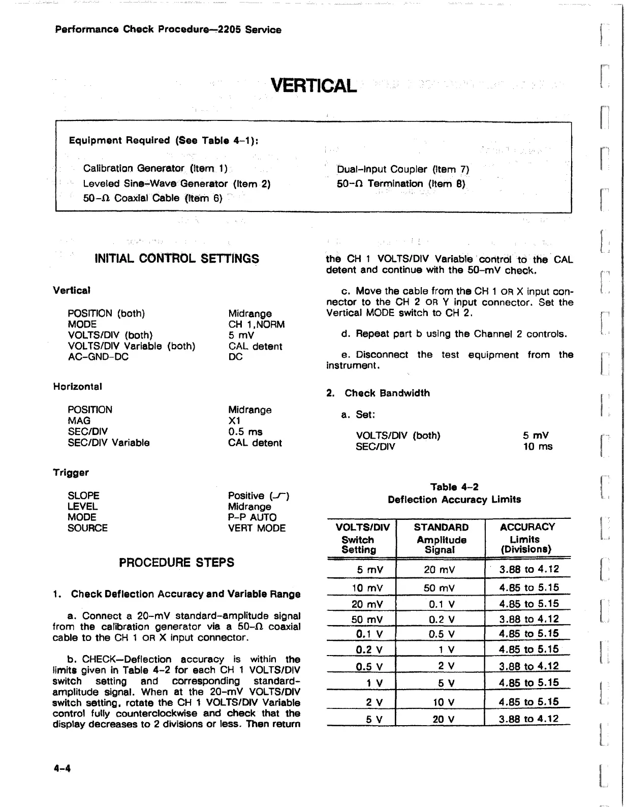
b. CHECK—Deflection accuracy is within the
limits given in Table 4-2 for each CH 1 VOLTS/DIV
switch setting and corresponding standard-
amplitude signal. When at the 20-mV VOLTS/DIV
switch setting, rotate the CH 1 VOLTS/DIV Variable
control fully counterclockwise and check that the
display decreases to 2 divisions or less. Then return
the CH 1 VOLTS/DIV Variable control to the CAL
detent and continue with the 50-mV check.
c. Move the cable from the CH 1 or X input con
nector to the CH 2 OR Y input connector. Set the
Vertical MODE switch to CH 2.
d. Repeat part b using the Channel 2 controls.
e. Disconnect the test equipment from the
instrument.
2. Check Bandwidth
a. Set:
VOLTS/DIV (both) 5 mV
SEC/DIV 10 ms
Table 4-2
Deflection Accuracy Limits
VOLTS/DIV
Switch
Setting
STANDARD
Amplitude
Signal
ACCURACY
Limits
(Divisions)
5 mV
20 mV
3.88 to 4.12
10 mV
50 mV
4.85 to 5.15
20 mV
0.1 V
4.85 to 5.15
50 mV
0.2 V
3.88 to 4.12
0.1 V 0.5 V
4.85 to 5.15
0.2 V
1 V 4.85 to 5.15
0.5 V
2 V
3.88 to 4.12
1 V 5 V
4.85 to 5.15
2 V 10 V
4.85 to 5.15
5 V
20 V
3.88 to 4.12
4-4

 Loading...


