Adjustment Procedure—2230 Service
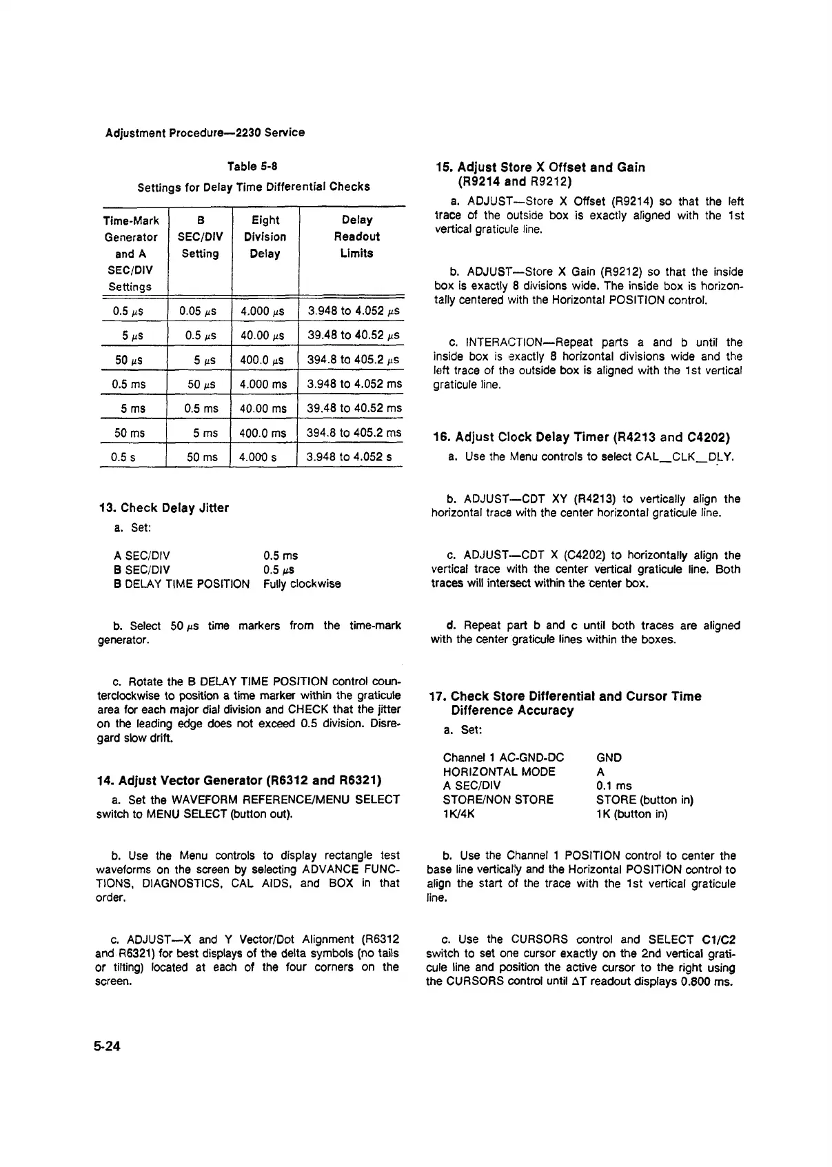
Table 5-8
Settings for Delay Time Differential Checks
Time-Mark
Generator
and A
SEC/DIV
Settings
B
SEC/DIV
Setting
Eight
Division
Delay
Delay
Readout
Limits
0.5 mS 0.05 ms 4.000 ms
3.948 to 4.052 mS
5 ms
0.5 mS 40.00 mS
39.48 to 40.52 mS
50 tiS
5 M s 400.0 mS
394.8 to 405.2 Ms
0.5 ms 50 ns 4.000 ms
3.948 to 4.052 ms
5 ms 0.5 ms 40.00 ms
39.48 to 40.52 ms
50 ms 5 ms
400.0 ms
394.8 to 405.2 ms
0.5 s 50 ms 4.000 s
3.948 to 4.052 s
13. Check Delay Jitter
a. Set:
A SEC/DIV 0.5 ms
B SEC/DIV 0.5 /<s
B DELAY TIME POSITION Fully clockwise
b. Select 50 ms time markers from the time-mark
generator.
15. Adjust Store X Offset and Gain
(R9214 and R9212)
a. ADJUST—Store X Offset (R9214) so that the left
trace of the outside box is exactly aligned with the 1st
vertical graticule line.
b. ADJUST—Store X Gain (R9212) so that the inside
box is exactly 8 divisions wide. The inside box is horizon
tally centered with the Horizontal POSITION control.
c. INTERACTION—Repeat parts a and b until the
inside box is exactly 8 horizontal divisions wide and the
left trace of the outside box is aligned with the 1 st vertical
graticule line.
16. Adjust Clock Delay Timer (R4213 and C4202)
a. Use the Menu controls to select CAL
_
CLK
_
DLY.
b. ADJUST—CDT XY (R4213) to vertically align the
horizontal trace with the center horizontal graticule line.
c. ADJUST—CDT X (C4202) to horizontally align the
vertical trace with the center vertical graticule line. Both
traces will intersect within the center box.
d. Repeat part b and c until both traces are aligned
with the center graticule lines within the boxes.
c. Rotate the B DELAY TIME POSITION control coun
terclockwise to position a time marker within the graticule
area for each major dial division and CHECK that the jitter
on the leading edge does not exceed 0.5 division. Disre
gard slow drift.
14. Adjust Vector Generator (R6312 and R6321)
a. Set the WAVEFORM REFERENCE/MENU SELECT
switch to MENU SELECT (button out).
17. Check Store Differential and Cursor Time
Difference Accuracy
a. Set:
Channel 1 AC-GND-DC
HORIZONTAL MODE
A SEC/DIV
STORE/NON STORE
1K/4K
GND
A
0.1 ms
STORE (button in)
1K (button in)
b. Use the Menu controls to display rectangle test
waveforms on the screen by selecting ADVANCE FUNC
TIONS, DIAGNOSTICS, CAL AIDS, and BOX in that
order.
b. Use the Channel 1 POSITION control to center the
base line vertically and the Horizontal POSITION control to
align the start of the trace with the 1st vertical graticule
line.
c. ADJUST—X and Y Vector/Dot Alignment (R6312
and R6321) for best displays of the delta symbols (no tails
or tilting) located at each of the four corners on the
screen.
c. Use the CURSORS control and SELECT C1/C2
switch to set one cursor exactly on the 2nd vertical grati
cule line and position the active cursor to the right using
the CURSORS control until AT readout displays 0.800 ms.
5-24

 Loading...


