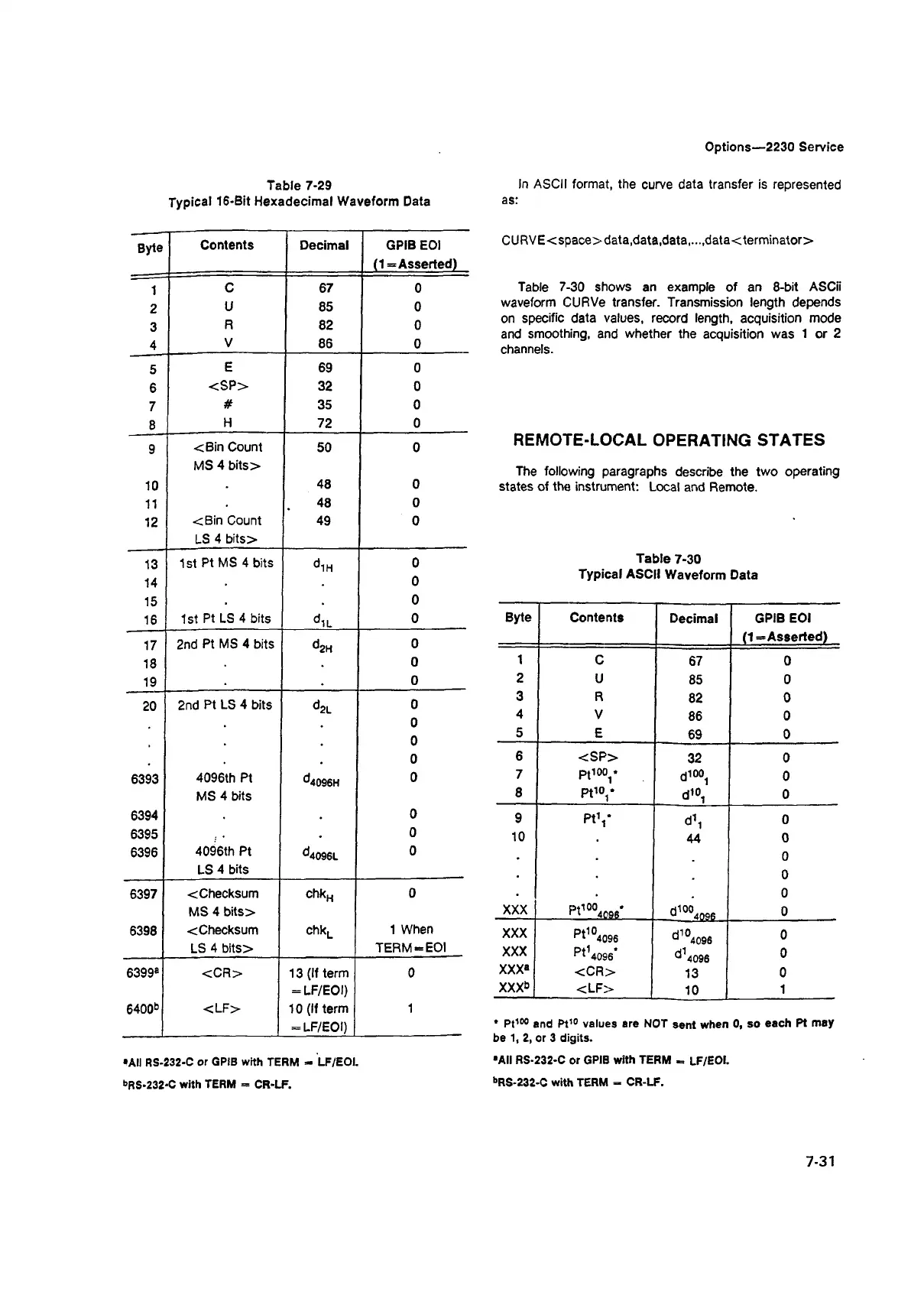
Table 7-29
Typical 16-Bit Hexadecimal Waveform Data
Options—2230 Service
In ASCII format, the curve data transfer is represented
as:
Byte
Contents Decimal GPIB EOI
(1= Asserted)
1
C 67
0
2
U
85 0
3
R
82 0
4
V
86
0
5
E
69
0
6
<SP>
32 0
7
#
35 0
8
H
72
0
9
<Bin Count
MS 4 bits>
50 0
10
48 0
11
48
0
12
<Bin Count
LS 4 bits>
49
0
13
1st Pt MS 4 bits
d 1H
0
14
0
15
0
16
1st Pt LS 4 bits
diL
0
17
2nd Pt MS 4 bits
d 2H
0
18
♦
0
19
.
0
20
2nd Pt LS 4 bits
d 2L
0
0
0
.
0
6393
4096th Pt
MS 4 bits
d4096H
0
6394
.
0
6395
.
0
6396
4096th Pt
LS 4 bits
d4096L
0
6397
< Checksum
MS 4 bits>
z
£1
O
0
6398
cChecksum
LS 4 bits>
chkL
1 When
TERM-EOI
6399®
<CR>
13 (If term
= LF/EOI)
0
6400b
<LF>
10 (If term
= LF/EOI)
1
•All RS-232-C or GPIB with TERM - LF/EOI.
bRS-232-C with TERM = CR-LF.
CURVE<space>data,data,data
....
data<terminator>
Table 7-30 shows an example of an 8-bit ASCii
waveform CURVe transfer. Transmission length depends
on specific data values, record length, acquisition mode
and smoothing, and whether the acquisition was 1 or 2
channels.
REMOTE-LOCAL OPERATING STATES
The following paragraphs describe the two operating
states of the instrument: Local and Remote.
Table 7-30
Typical ASCII Waveform Data
Byte
Contents
Decimal
GPIB EOI
(1—Asserted)
1
C
67
0
2
U
85
0
3
R
82
0
4
V
86
0
5
E
69
0
6
<SP>
32
0
7
Pt100/
d100.
0
8
Pt10,*
d10,
0
9
Pt1,*
d,i
0
10
44
0
. .
0
0
0
XXX
P t10°4Q96-
d1004n«s
0
XXX
Pt104096
d1°4096
0
XXX
Pt14096*
d14096
0
XXX®
<C R >
13
0
XXX6
<LF>
10
1
* Pt100 and Pt10 values are NOT sent when 0, so each Pt may
be 1, 2, or 3 digits.
■All RS-232-C or GPIB with TERM = LF/EOI.
bRS-232-C with TERM = CR-LF.
7-31

 Loading...


