Operating Information—2230 Service
The STORE mode display is the A Intensified
trace only. The intensified zone on the A trace
indicates the approximate delay position and
length of the B Delayed Sweep. The displayed
position of the intensified zone is updated after
each trigger. The A SEC/DIV, B SEC/DIV, and B
DELAY TIME POSITION settings are displayed
on the crt readout. In BOTH, STORE mode
acquisitions are controlled by the A SEC/DIV
switch.
B—Displays either the NON STORE or the
STORE B Sweep trace. The A SEC/DIV, B
SEC/DIV, and B DELAY TIME POSITION settings
are displayed on the crt readout, just as in BOTH.
The STORE mode waveform acquisitions are con
trolled by the B SEC/DIV switch.
0
) B DELAY TIME POSITION Control—Adjusts the
delay between the start time of the A Sweep and the
time that the B Sweep either starts (RUNS AFTER
DLY) or can be triggered (Triggerable After Dly). (The
A Sweep does not have to be displayed.) The delay
time is variable from 0.5 to 10 times the A SEC/DIV,
plus 300 ns.
In Triggerable After Delay, the delay time readout
indicates the time that must elapse after the A
trigger before the delayed sweep or delayed acquisi
tion can be triggered; not the actual position of the
trigger point. However, the readout of the delay time
on the crt follows the setting of the B DELAY TIME
POSITION control in either B Trigger mode.
The setting of the 1K/4K switch affects the delay
time position setting for STORE mode displays by a
factor of approximately four times. When switching
between IK and 4K record lengths, the delay time
position setting must be readjusted to obtain the
same delay time.
0 ) Horizontal POSITION Control— Positions all the
NON STORE waveforms horizontally over a one-
sweep-length range (either XI or X I0 Magnified).
Using the Horizontal POSITION control, STORE
mode waveforms may be positioned over a range of
only one display window. When a STORE mode
acquisition display is longer than one screen (as in
4K records and/or X I0 MAG), the CURSORS POSI
TION control is used to position the display window
to any position of the acquisition record. The Hor
izontal POSITION control does not position the crt
readout displays.
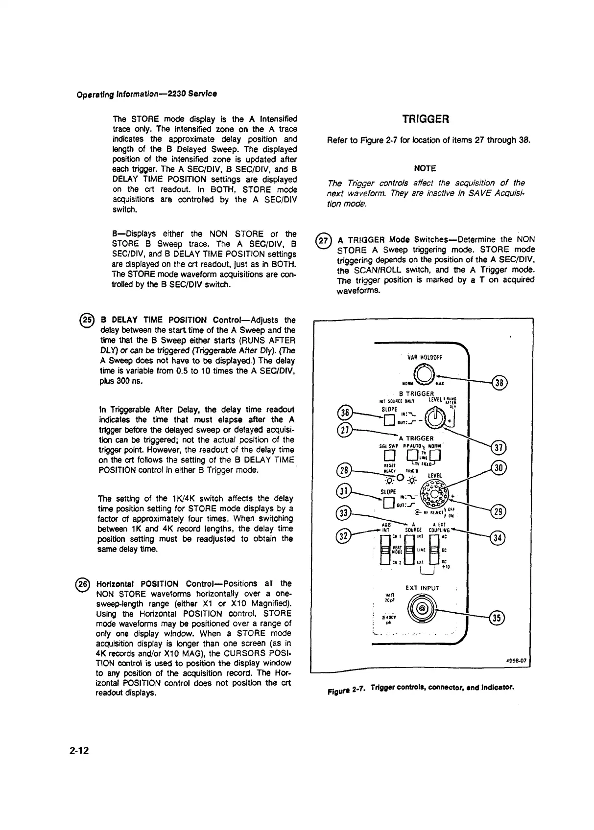
TRIGGER
Refer to Figure 2-7 for location of items 27 through 38.
NOTE
The Trigger controls affect the acquisition o f the
next waveform. They are inactive in SAVE Acquisi
tion mode.
(27) A TRIGGER Mode Switches—Determine the NON
STORE A Sweep triggering mode. STORE mode
triggering depends on the position of the A SEC/DIV,
the SCAN/ROLL switch, and the A Trigger mode.
The trigger position is marked by a T on acquired
waveforms.
Figure 2-7- Triflger controls, connector, end indicator.
2-12

 Loading...


