Options—2230 Service
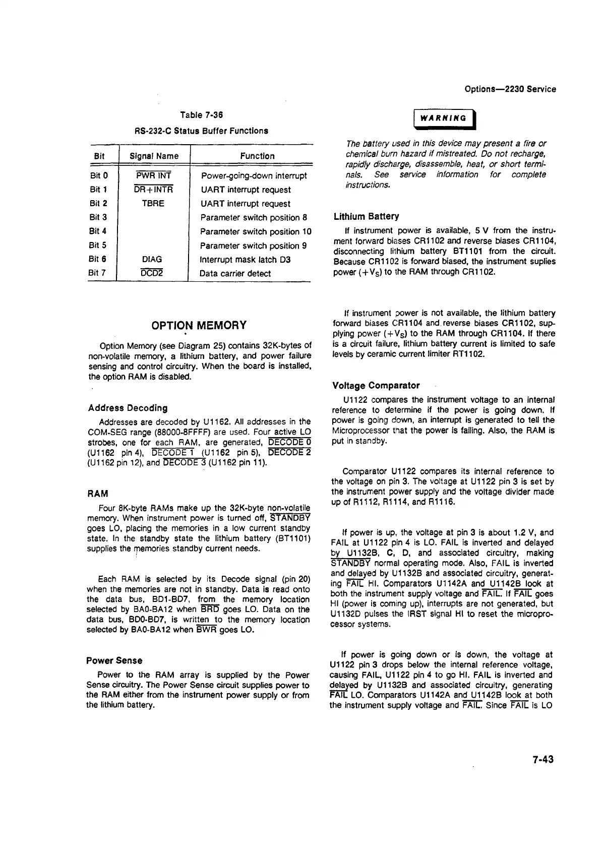
Table 7-36
RS-232-C Status Buffer Functions
Bit Signal Name Function
Bit 0 PWR INT
Power-going-down interrupt
Bit 1 DR + INTR UART interrupt request
Bit 2 TBRE
UART interrupt request
Bit 3
Parameter switch position 8
Bit 4
Parameter switch position 10
Bit5
Parameter switch position 9
Bit 6
DIAG
Interrupt mask latch D3
Bit 7 |
DCD2
Data carrier detect
OPTION MEMORY
Option Memory (see Diagram 25) contains 32K-bytes of
non-volatile memory, a lithium battery, and power failure
sensing and control circuitry. When the board is installed,
the option RAM is disabled.
Address Decoding
Addresses are decoded by U1162. All addresses in the
COM-SEG range (88000-8FFFF) are used. Four active LO
strobes, one for each RAM, are generated, DECODE 0
(U1162 pin 4), DECODE 1 (U1162 pin 5), DECODE 2
(U1162 pin 12), and DECODE 3 (U1162 pin 11).
RAM
Four 8K-byte RAMs make up the 32K-byte non-volatile
memory. When instrument power is turned off, STANDBY
goes LO, placing the memories in a low current standby
state. In the standby state the lithium battery (BT1101)
supplies the memories standby current needs.
Each RAM is selected by its Decode signal (pin 20)
when the memories are not in standby. Data is read onto
the data bus, BD1-BD7, from the memory location
selected by BA0-BA12 when BRD goes LO. Data on the
data bus, BD0-BD7, is written to the memory location
selected by BA0-BA12 when BWR goes LO.
Power Sense
Power to the RAM array is supplied by the Power
Sense circuitry. The Power Sense circuit supplies power to
the RAM either from the instrument power supply or from
the lithium battery.
WARNING
The battery used in this device may present a fire or
chemical burn hazard if mistreated. Do not recharge,
rapidly discharge, disassemble, heat, or short termi
nals. See service information for complete
instructions.
Lithium Battery
If instrument power is available, 5 V from the instru
ment forward biases CR1102 and reverse biases CR1104,
disconnecting lithium battery BT1101 from the circuit.
Because CR1102 is forward biased, the instrument suplies
power (+VS) to the RAM through CR1102.
If instrument power is not available, the lithium battery
forward biases CR1104 and reverse biases CR1102, sup
plying power (+VS) to the RAM through CR1104. If there
is a circuit failure, lithium battery current is limited to safe
levels by ceramic current limiter RT1102.
Voltage Comparator
U1122 compares the instrument voltage to an internal
reference to determine if the power is going down. If
power is going down, an interrupt is generated to tell the
Microprocessor that the power is failing. Also, the RAM is
put in standby.
Comparator U1122 compares its internal reference to
the voltage on pin 3. The voltage at U1122 pin 3 is set by
the instrument power supply and the voltage divider made
up of R1112, R1114, and R1116.
If power is up, the voltage at pin 3 is about 1.2 V, and
FAIL at U1122 pin 4 is LO. FAIL is inverted and delayed
by U1132B, C, D, and associated circuitry, making
STANDBY normal operating mode. Also, FAIL is inverted
and delayed by U1132B and associated circuitry, generat
ing FAIL HI. Comparators U1142A and U1142B look at
both the instrument supply voltage and FAIL. If FAIL goes
HI (power is coming up), interrupts are not generated, but
U1132D pulses the IRST signal HI to reset the micropro
cessor systems.
If power is going down or is down, the voltage at
U1122 pin 3 drops below the internal reference voltage,
causing FAIL, U1122 pin 4 to go HI. FAIL is inverted and
delayed by U1132B and associated circuitry, generating
FAIL LO. Comparators U1142A and U1142B look at both
the instrument supply voltage and FAIL. Since FAIL is LO
7-43

 Loading...


