Maintenance— 2230 Service
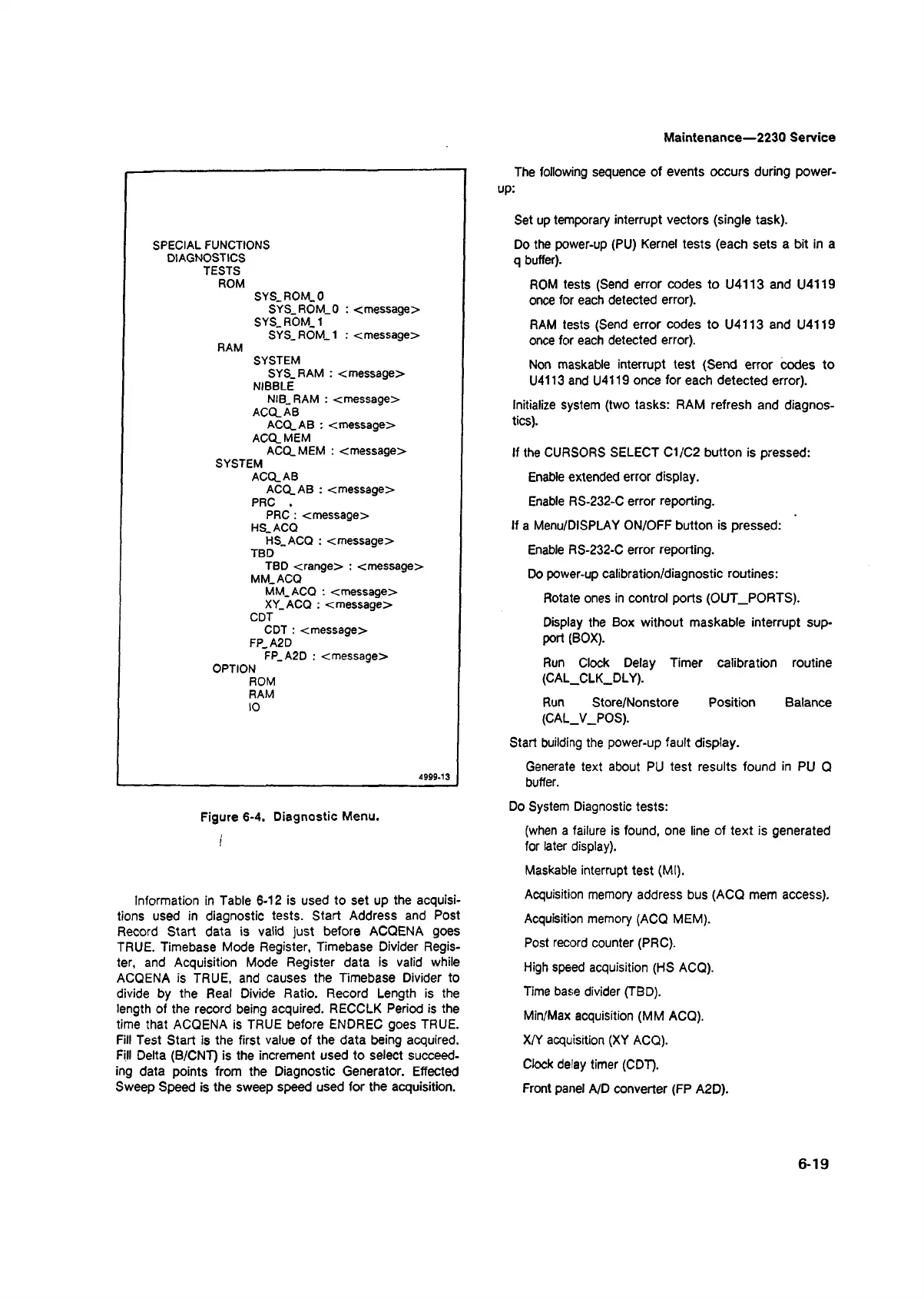
SPECIAL FUNCTIONS
DIAGNOSTICS
TESTS
ROM
SYS_ROM_0
SYS ROM_0 : <message>
SYS_ROM_1
SYS_ROM_1 : <message>
RAM
SYSTEM
SYS RAM : <message>
NIBBLE
NIB RAM : <message>
ACQ_AB
ACQ.AB : <message>
ACQ.MEM
ACQ. MEM : <message>
SYSTEM
ACQ.AB
ACQ.AB : <message>
PRC .
PRC : <message>
HS.ACQ
HS ACQ : <message>
TBD
TBD <range> : <message>
MM. ACQ
MM. ACQ : <message>
XY ACQ : <message>
CDT
CDT : <message>
FP.A2D
FP A2D : <message>
OPTION
ROM
RAM
10
4999-13
Figure 6-4. Diagnostic Menu.
Information in Table 6-12 is used to set up the acquisi
tions used in diagnostic tests. Start Address and Post
Record Start data is valid just before ACQENA goes
TRUE. Timebase Mode Register, Timebase Divider Regis
ter, and Acquisition Mode Register data is valid while
ACQENA is TRUE, and causes the Timebase Divider to
divide by the Real Divide Ratio. Record Length is the
length of the record being acquired. RECCLK Period is the
time that ACQENA is TRUE before ENDREC goes TRUE.
Fill Test Start is the first value of the data being acquired.
Fill Delta (B/CNT) is the increment used to select succeed
ing data points from the Diagnostic Generator. Effected
Sweep Speed is the sweep speed used for the acquisition.
The following sequence of events occurs during power-
x
Set up temporary interrupt vectors (single task).
Do the power-up (PU) Kernel tests (each sets a bit in a
q buffer).
ROM tests (Send error codes to U4113 and U4119
once for each detected error).
RAM tests (Send error codes to U4113 and U4119
once for each detected error).
Non maskable interrupt test (Send error codes to
U4113 and U4119 once for each detected error).
Initialize system (two tasks: RAM refresh and diagnos
tics).
If the CURSORS SELECT C1/C2 button is pressed:
Enable extended error display.
Enable RS-232-C error reporting.
If a Menu/DISPLAY ON/OFF button is pressed:
Enable RS-232-C error reporting.
Do power-up calibration/diagnostic routines:
Rotate ones in control ports (OUT_PORTS).
Display the Box without maskable interrupt sup
port (BOX).
Run Clock Delay Timer calibration routine
(CAL_CLK_DLY).
Run Store/Nonstore Position Balance
(CAL_V_POS).
Start building the power-up fault display.
Generate text about PU test results found in PU Q
buffer.
Do System Diagnostic tests:
(when a failure is found, one line of text is generated
for later display).
Maskable interrupt test (Ml).
Acquisition memory address bus (ACQ mem access).
Acquisition memory (ACQ MEM).
Post record counter (PRC).
High speed acquisition (HS ACQ).
Time base divider (TBD).
Min/Max acquisition (MM ACQ).
X/Y acquisition (XY ACQ).
Clock delay timer (CDT).
Front panel A/D converter (FP A2D).
6-19

 Loading...


