Specification—2465B/2467B Service
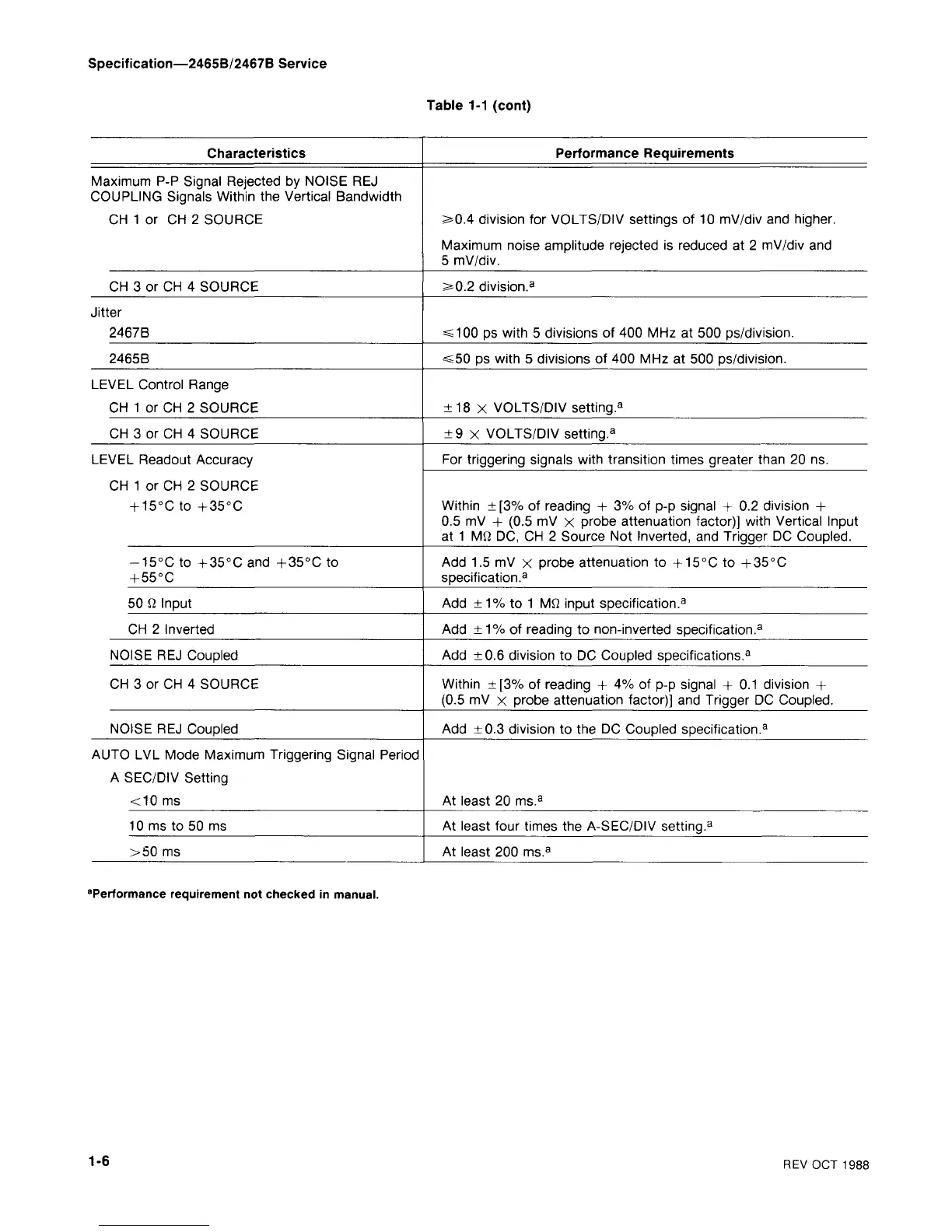
Table 1-1 (cont)
Characteristics
Maximum P-P Signal Rejected by NOISE REJ
COUPLING Signals Within the Vertical Bandwidth
CH 1 or CH 2 SOURCE
CH 3 or CH 4 SOURCE
Jitter
2467 B
2465B
LEVEL Control Range
CH 1 or CH 2 SOURCE
CH 3 or CH 4 SOURCE
LEVEL Readout Accuracy
CH 1 or CH 2 SOURCE
+ 15°C to +35°C
-15°C to + 35°C and +35°C to
+ 55°C
50 fi Input
CH 2 Inverted
NOISE REJ Coupled
CH 3 or CH 4 SOURCE
NOISE REJ Coupled
AUTO LVL Mode Maximum Triggering Signal Period
A SEC/DIV Setting
<10 ms
10 ms to 50 ms
>50 ms
Performance Requirements
>0.4 division for VOLTS/DIV settings of 10 mV/div and higher.
Maximum noise amplitude rejected is reduced at 2 mV/div and
5 mV/div.
2*0.2 division.
3
=s100 ps with 5 divisions of 400 MHz at 500 ps/division.
<50 ps with 5 divisions of 400 MHz at 500 ps/division.
±18 x VOLTS/DIV setting.
3
±9 x VOLTS/DIV setting.
3
For triggering signals with transition times greater than 20 ns.
Within ± [3% of reading + 3% of p-p signal + 0.2 division +
0.5 mV + (0.5 mV x probe attenuation factor)] with Vertical Input
at 1 Mfi DC, CH 2 Source Not Inverted, and Trigger DC Coupled.
Add 1.5 mV x probe attenuation to +15°C to + 35°C
specification.
3
Add
±1%
to 1 Mfi input specification.
3
Add
±1%
of reading to non-inverted specification.
3
Add ±0.6 division to DC Coupled specifications.
3
Within ±[3% of reading + 4% of p-p signal + 0.1 division +
(0.5 mV x probe attenuation factor)] and Trigger DC Coupled.
Add ±0.3 division to the DC Coupled specification.
3
At least 20 ms.
3
At least four times the A-SEC/DIV setting.
3
At least 200 ms.
3
"Performance requirement not checked in manual.
1-6
REV OCT 1988

 Loading...


