Section 10—2465B/2467B Service
DIAGRAMS
AND
CIRCUIT BOARD ILLUSTRATIONS
Symbols
Graphic symbols
and
class designation letters
are
based
on
ANSI Standard Y32.2-1975.
Logic symbology
is
based
on
ANSI Y32.14-1973
in
terms
of
positive logic. Logic symbols depict
the
logic
function performed
and may
differ from
the
manufac-
turer's data.
The overline
on a
signal name indicates that the signal
performs
its
intended function when
it is in the low
state.
Abbreviations
are
based
on
ANSI Y1.1-1972.
Other ANSI standards that
are
used
in the
preparation
of diagrams
by
Tektronix,
Inc. are:
Y14.15,
1966
Drafting Practices.
Y14.2,
1973
Line Conventions
and
Lettering.
Y10.5,
1968
Letter Symbols
for
Quantities Used
in
Electrical Science
and
Electrical
Engineering.
American National Standard Institute
1430 Broadway
New York,
New
York
10018
Component Values
Electrical components shown
on the
diagrams
are in
the following units unless noted otherwise:
Capacitors
=
Values one
or
greater are in picofarads (pF).
Values less than
one are in
microfarads
foF).
Resistors
=
Ohms
(O).
The information
and
special symbols below
may
appear
in
this manual.-
Assembly Numbers
and
Grid Coordinates
Each assembly
in the
instrument
is
assigned
an
assembly number
(e.g.,
A20). The
assembly number
appears on
the
circuit board outline on the diagram, in the
title
for the
circuit board component location illustration,
and
in the
lookup table
for the
schematic diagram
and
corresponding component locator illustration.
The
Replaceable Electrical Parts list is arranged by assemblies
in numerical sequence;
the
components
are
listed
by
component number
"(see
following illustration
for
constructing
a
component number).
The schematic diagram
and
circuit board component
location illustration have grids.
A
lookup table with
the
grid coordinates
is
provided
for
ease
of
locating
the
component. Only the components illustrated on thefacing
diagram
are
listed
in the
lookup table. When more than
one schematic diagram is used
to
illustratethe circuitry
on
a circuit board,
the
circuit board illustration
may
only
appear opposite
the
first diagram
on
which
it
was il-
lustrated;
the
lookup table will list
the
diagram number
of
other diagrams that
the
circuitry
of the
circuit board
appears
on.
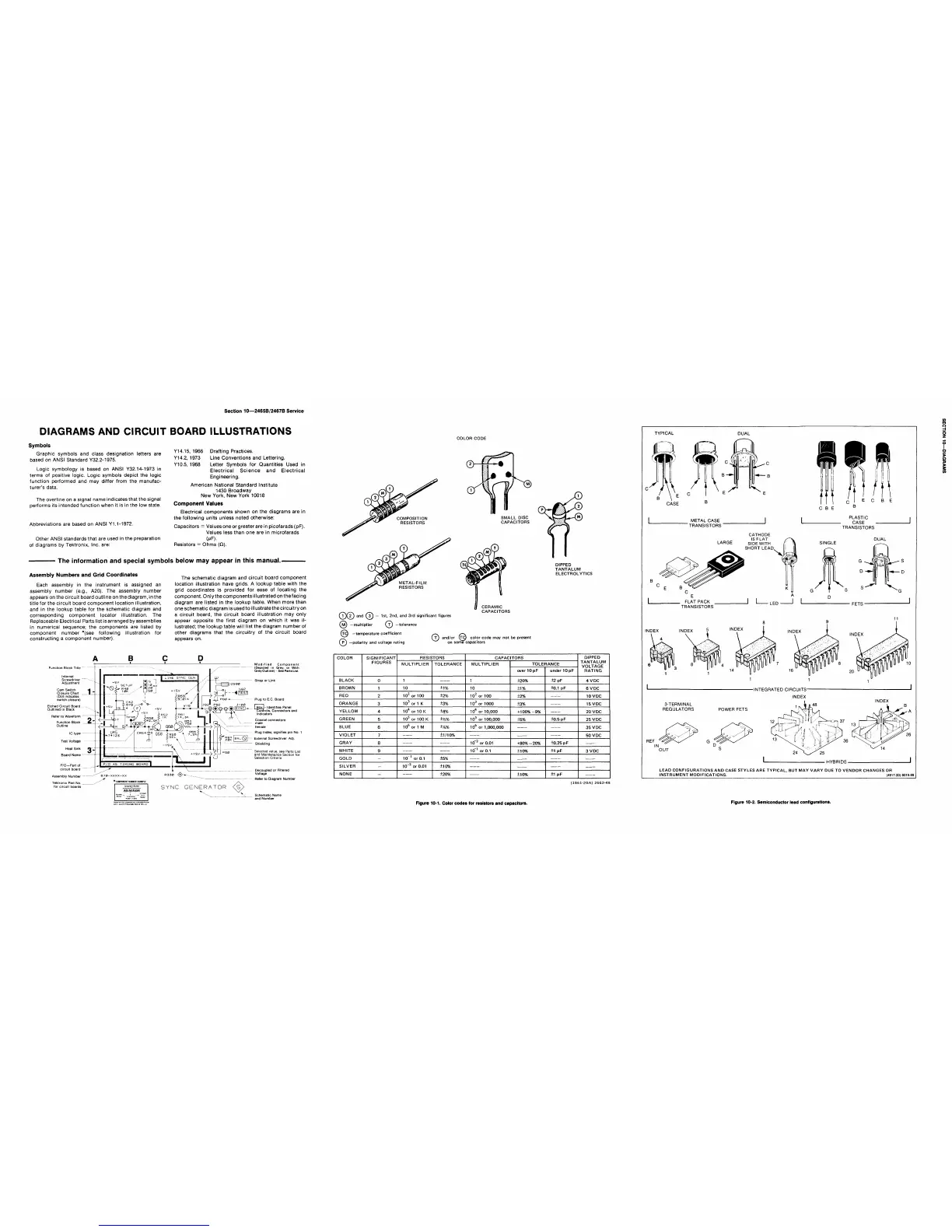
COLOR CODE
DIPPED
TANTALUM
ELECTROLYTICS
COCO
and f3J — 1st, 2nd, and 3rd
significant figures
fMJ —multiplier
Qn
—tolerance
n"g —temperature coefficient
CERAMIC
CAPACITORS
©
-polarity and voltage rating
m and/or
(rd)
color code may
not
be present
on some capacitors
Function Block Title
Cam Switch
Closure Chart
,
(Dot indicates
switch closure)
Etched Circuit Board
Outlined
in
Black
Refer
to
Waveform
Function Block
Outline
P/O—Part
of
circuit board
Assembly Number
Tektronix Part No....
for circuit boards
670-XXXX-XX
"
*
COMPONENT NUMBER EMM PIE
M3A2R1234
R330
<3>^
SYNC GENERATOR
Modified Component
(Depicted
in
Grey,
or
With
Grey
Outline)
-
See Parts
List.
Strap
or
Link
Plug
to
E.C. Board
Box
I-
Identifies Panel
Controls, Connectors and
Indicators
Coaxial connectors:
male
female
Plug Index; signifies
pin
No.
1
External Screwdriver
Adj.
Shielding
Selected value,
see
Parts List
and Maintenance Section
for
Selection Criteria
Decoupled
or
Filtered
Voltage
Refer
to
Diagram Number
Schematic Name
and Number
COLOR
BLACK
BROWN
RED
ORANGE
YELLOW
GREEN
BLUE
VIOLET
GRAY
WHITE
GOLD
SILVER
NONE
SIGNIFICANT
FIGURES
0
1
2
3
4
5
6
7
8
9
-
-
-
RESISTORS
MULTIPLIER
1
10
10
2
or 100
10
3
or
1
K
10
4
or 10 K
10
5
or 100 K
10
6
or
1
M
10"
1
or 0.1
10~
2
or 0.01
TOLERANCE
±1%
±2%
±3%
±4%
±14%
±Y*%
±1/10%
±5%
±10%
±20%
CAPACITORS
MULTIPLIER
1
10
10
2
or 100
10
3
or 1000
10
4
or
10,000
10
s
or
100,000
10
6
or
1,000,000
10~
2
or 0.01
10"
1
or 0.1
TOLERANCE
over
10 pF
±20%
±1%
±2%
±3%
+100%
-9%
±5%
+80%
-20%
±10%
±10%
under
10pF
±2pF
±0.1
pF
±0.5
pF
±0.25
pF
±1
pF
±1
pF
DIPPED
TANTALUM
VOLTAGE
RATING
4VDC
6VDC
10VDC
15VDC
20 V DC
25VDC
35 V DC
50
VDC
3
VDC
(1861-20A) 2662-48
Figure
10-1.
Color codes for resistors and capacitors.
TYPICAL
DUAL
CASE
C
B E
METAL CASE
"TRANSISTORS
PLASTIC
CASE
TRANSISTORS
CATHODE
IS FLAT
, „
LARGE SIDE WITH
I' *
SHORT LEAD
SINGLE
DUAL
m
. FLAT PACK
TRANSISTORS
LED
FETS"
INDEX
INDEX
■INTEGRATED CIRCUITS-
INDEX
3-TERMINAL
REGULATORS
INDEX
POWER FETS
REF
OUT
■
HYBRIDS-
LEAD CONFIGURATIONS
AND
CASE STYLES
ARE
TYPICAL,
BUT MAY
VARY
DUE TO
VENDOR CHANGES
OR
INSTRUMENT MODIFICATIONS. (4917-33)6019-99
Figure 10-2. Semiconductor lead configurations.

 Loading...


