Adjustment Procedure—2465B/2467B Service
Table
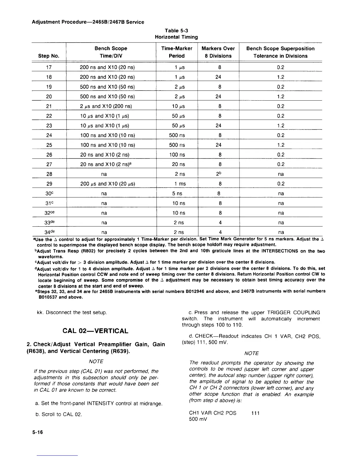
5-3
Horizontal Timing
Step
No.
17
18
19
20
21
22
23
24
25
26
27
28
29
30°
31
c
32
ce
33
de
34
de
Bench Scope
Time/DIV
200
ns and
X10(20ns)
200
ns
and X10 (20
ns)
500
ns and
X10(50
ns)
500
ns and
X10(50
ns)
2 MS and X10 (200
ns)
10 MS and X10
(1
MS)
10 MS and X10(1
us)
100
ns
and X10 (10
ns)
100
ns and
X10(10
ns)
20
ns
and X10(2
ns)
20
ns
and X10(2 ns)
a
na
200 MS and X10 (20
MS)
na
na
na
na
na
Time-Marker
Period
1
MS
1
MS
2
MS
2
MS
10 MS
50 MS
50 MS
500 ns
500 ns
100
ns
20
ns
2
ns
1
ms
5
ns
10
ns
10 ns
2
ns
2 ns
Markers Over
8 Divisions
8
24
8
24
8
8
24
8
24
8
8
2
b
8
8
8
8
4
4
Bench Scope Superposition
Tolerance
in
Divisions
0.2
1.2
0.2
1.2
0.2
0.2
1.2
0.2
1.2
0.2
0.2
na
0.2
na
na
na
na
na
"Use
the A
control
to
adjust
for
approximately
1
Time-Marker
per
division.
Set
Time Mark Generator
for 5 ns
markers. Adjust
the A
control
to
superimpose
the
displayed bench scope display.
The
bench scope holdoff
may
require adjustment.
b
Adjust Trans Resp (R802)
for
precisely
2
cycles between
the 2nd and 10th
graticule lines
at the
INTERSECTIONS
on the two
waveforms.
c
Adjust volt/div
for > 3
division amplitude. Adjust
A for
1 time marker
per
division over
the
center
8
divisions.
d
Adjust volt/div
for 1 to 4
division amplitude. Adjust
A for 1
time marker
per 2
divisions over
the
center
8
divisions.
To do
this,
set
Horizontal Position control CCW
and
note
end of
sweep timing over
the
center
8
divisions. Return Horizontal Position control
CW to
locate beginning
of
sweep. Some compromise
of the A
adjustment
may be
necessary
to
obtain best timing accuracy over
the
center
8
divisions
at the
start and
end of
sweep.
e
Steps 32,
33, and 34 are for
2465B instruments with serial numbers B012946
and
above,
and
2467B instruments with serial numbers
B010537
and
above.
kk. Disconnect
the
test setup.
CAL 02—VERTICAL
2.
Check/Adjust Vertical Preamplifier Gain, Gain
(R638),
and Vertical Centering (R639).
NOTE
If
the
previous step
(CAL 01) was not
performed,
the
adjustments
in
this subsection should only
be per-
formed
if
those constants that would have been
set
in
CAL 01 are
known
to be
correct.
a.
Set the
front-panel INTENSITY control
at
midrange.
b. Scroll
to CAL 02.
c. Press
and
release
the
upper TRIGGER COUPLING
switch.
The
instrument will automatically increment
through steps
100 to 110.
d.
CHECK—Readout indicates
CH 1 VAR, CH2 POS,
(step) 111,
500 mV.
NOTE
The readout prompts
the
operator
by
showing
the
controls
to be
moved (upper left corner
and
upper
center),
the
autocal step number (upper right corner),
the amplitude
of
signal
to be
applied
to
either
the
CH
1 or CH 2
connectors (lower left corner),
and any
other scope function that
is
enabled.
An
example
(from step
d
above)
is:
CH1
VAR CH2 POS
500
mV
111
5-16

 Loading...


