Adjustment Procedure—246SB/2467B Service
e. Connect a 0.5 V, standard-amplitude signal from the
Calibration Generator to the CH 1 OR X input connector
via a 50
Q
BNC cable.
f. Use the CH 2 POSITION control to vertically position
the trace to within 1 division of the center graticule line.
g.
ADJUST—CH 1 POSITION and VOLTS/DIV VAR
controls to obtain a 10-division horizontal signal. Press
and release the upper TRIGGER COUPLING switch.
NOTE
When step 111 is performed, step 112 is also
automatically done. No indication of step 112 will be
shown unless a LIMIT error is indicated.
NOTE
In the following steps, if the
"LIMIT"
message
appears, it probably indicates that the TRIGGER
COUPLING (step) switch was moved before the
required signal was applied. Press and release the
lower TRIGGER COUPLING switch, verify that the
correct signal is applied, then press and release the
upper TRIGGER COUPLING switch.
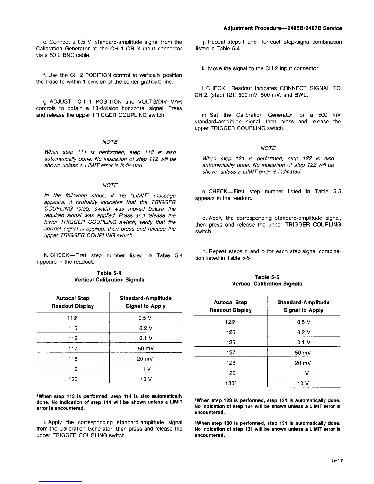
h. CHECK—First step number listed in Table 5-4
appears in the readout.
Table 5-4
Vertical Calibration Signals
Autocal Step
Readout Display
113
a
115
116
117
118
119
120
Standard-Amplitude
Signal to Apply
0.5 V
0.2 V
0.1 V
50 mV
20 mV
1 V
10 V
"When step 113 is performed, step 114 is also automatically
done.
No indication of step 114 will be shown unless a LIMIT
error is encountered.
i. Apply the corresponding standard-amplitude signal
from the Calibration Generator, then press and release the
upper TRIGGER COUPLING switch.
j.
Repeat steps h and i for each step-signal combination
listed in Table 5-4.
k. Move the signal to the CH 2 input connector.
I. CHECK—Readout indicates CONNECT SIGNAL TO
CH 2, (step) 121, 500 mV, 500 mV, and BWL
m. Set the Calibration Generator for a 500 mV
standard-amplitude signal, then press and release the
upper TRIGGER COUPLING switch.
NOTE
When step 121 is performed, step 122 is also
automatically done. No indication of step 122 will be
shown unless a LIMIT error is indicated.
n. CHECK—First step number listed in Table 5-5
appears in the readout.
o. Apply the corresponding standard-amplitude signal,
then press and release the upper TRIGGER COUPLING
switch.
p. Repeat steps n and o for each step-signal combina-
tion listed in Table 5-5.
Table 5-5
Vertical Calibration Signals
Autocal Step
Readout Display
123
a
125
126
127
128
129
130
b
Standard-Amplitude
Signal to Apply
0.5 V
0.2 V
0.1 V
50 mV
20 mV
1 V
10V
"When step 123 is performed, step 124 is automatically done.
No indication of step 124 will be shown unless a LIMIT error is
encountered.
b
When step 130 is performed, step 131 is automatically done.
No indication of step 131 will be shown unless a LIMIT error is
encountered.
5-17

 Loading...


