Theory of Operation—2465B/2467B Service
Inverting the Channel 2 signal for the CH 2 INVERT
feature is accomplished by biasing on different amplifiers.
The control data clocked into the internal control register
from pin 22 sets up the necessary switching.
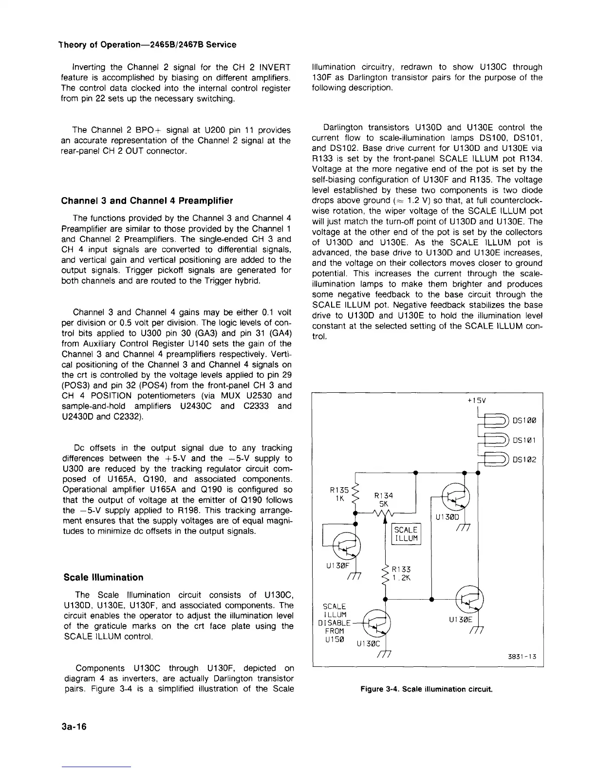
Illumination circuitry, redrawn to show U130C through
130F as Darlington transistor pairs for the purpose of the
following description.
The Channel 2 BPO+ signal at U200 pin 11 provides
an accurate representation of the Channel 2 signal at the
rear-panel CH 2 OUT connector.
Channel 3 and Channel 4 Preamplifier
The functions provided by the Channel 3 and Channel 4
Preamplifier are similar to those provided by the Channel 1
and Channel 2 Preamplifiers. The single-ended CH 3 and
CH 4 input signals are converted to differential signals,
and vertical gain and vertical positioning are added to the
output signals. Trigger pickoff signals are generated for
both channels and are routed to the Trigger hybrid.
Channel 3 and Channel 4 gains may be either 0.1 volt
per division or 0.5 volt per division. The logic levels of
con-
trol bits applied to U300 pin 30 (GA3) and pin 31 (GA4)
from Auxiliary Control Register U140 sets the gain of the
Channel 3 and Channel 4 preamplifiers respectively. Verti-
cal positioning of the Channel 3 and Channel 4 signals on
the crt is controlled by the voltage levels applied to pin 29
(POS3) and pin 32 (POS4) from the front-panel CH 3 and
CH 4 POSITION potentiometers (via MUX U2530 and
sample-and-hold amplifiers U2430C and C2333 and
U2430D and C2332).
Dc offsets in the output signal due to any tracking
differences between the + 5-V and the -5-V supply to
U300 are reduced by the tracking regulator circuit com-
posed of U165A, Q190, and associated components.
Operational amplifier U165A and Q190 is configured so
that the output of voltage at the emitter of Q190 follows
the -5-V supply applied to R198. This tracking arrange-
ment ensures that the supply voltages are of equal magni-
tudes to minimize dc offsets in the output signals.
Scale Illumination
The Scale Illumination circuit consists of U130C,
U130D,
U130E, U130F, and associated components. The
circuit enables the operator to adjust the illumination level
of the graticule marks on the crt face plate using the
SCALE ILLUM control.
Components U130C through U130F, depicted on
diagram 4 as inverters, are actually Darlington transistor
pairs.
Figure 3-4 is a simplified illustration of the Scale
Darlington transistors U130D and U130E control the
current flow to scale-illumination lamps DS100,
DS101,
and DS102. Base drive current for U130D and U130E via
R133 is set by the front-panel SCALE ILLUM pot R134.
Voltage at the more negative end of the pot is set by the
self-biasing configuration of U130F and R135. The voltage
level established by these two components is two diode
drops above ground (=s 1.2 V) so that, at full counterclock-
wise rotation, the wiper voltage of the SCALE ILLUM pot
will just match the turn-off point of U130D and U130E. The
voltage at the other end of the pot is set by the collectors
of U130D and U130E. As the SCALE ILLUM pot is
advanced,
the base drive to U130D and U130E increases,
and the voltage on their collectors moves closer to ground
potential.
This increases the current through the scale-
illumination lamps to make them brighter and produces
some negative feedback to the base circuit through the
SCALE ILLUM pot. Negative feedback stabilizes the base
drive to U130D and U130E to hold the illumination level
constant at the selected setting of the SCALE ILLUM
con-
trol.
-15V
U130F
SCALE
ILLUM
DISABLE
FROM
U150
SCALE
LLUM
U130D
m
3) DSI00
D)DS101
D) DS102
U130C
m
3851-13
Figure 3-4. Scale illumination circuit.
3a-16

 Loading...


