Trigger Setup
Specific byte matching (non-rolling window matching for a specific position in the packet) for I
2
C, SPI,
USB, CAN, and FlexRay.
You c an trigger on a specificbyteforI
2
C, SPI, C AN, and FlexRay in several ways:
For I
2
C and SPI, enter the number of bytes to match the number of bytes in the signal. Then use don’t cares (X) to
mask the byte
s that you are not interested in.
For I
2
C, push
the lower-bezel Trigger On to trigger on Address/Data. Push Address. O n the side-bezel menu, push
Address, and rotate multipurpose knobs a and b as needed. Set the address to don’t cares (X) if you want to mask the
address. The data will be matched starting at the first byte without using a rolling window.
For USB, triggering occurs when the user-selected data input matches the data and qualifier in the signal starting at
thebyteoff
set. Set the number of bytes to match the number of bytes of interest. Use the data qualifier to perform: =,
!=, <, >, >=, and <= operations.
For CAN, triggering occurs when the user-selected data input matches the data and qualifier in the signal starting at
the first byte. S et the number of bytes to match the number of bytes of interest. Use the data qualifier to perform: =,
!=,<,>,>=
, and <= operations. Triggering on identifier and data always matches the identifier and data selected by
the user, with the data starting at the first byte. No rolling window is used.
For FlexRay and Ethernet, triggering occurs w hen the user-selected data input matches the data and qualifier in the
signal starting at the byte offset. Set the number of bytes to match the number of bytes of interest. Use the data quali fier
to perfor
m: =, !=, <, >, >=, and <= operations. Triggering on identifier and data always matches the identifier and data
selected by the user, with the data starting at the first byte. No rolling window is used.
Data Value Matching
You can trigger on a specific data value for RS-232 bytes. If you defined an end-of-packet character to use for RS-232 bus
decoding, you can use the same end-of-packet character as a data value for trigger data matching. To do so, choose the Tx
End of Packet or the Rx End of Packet character as the Trigger On selection.
You can also trigger on a specific data value for other buses.
ParallelBusTriggerDataMatching
Optimum parallel bus trigger performance is achieved by using only analog channels or only digital channels.
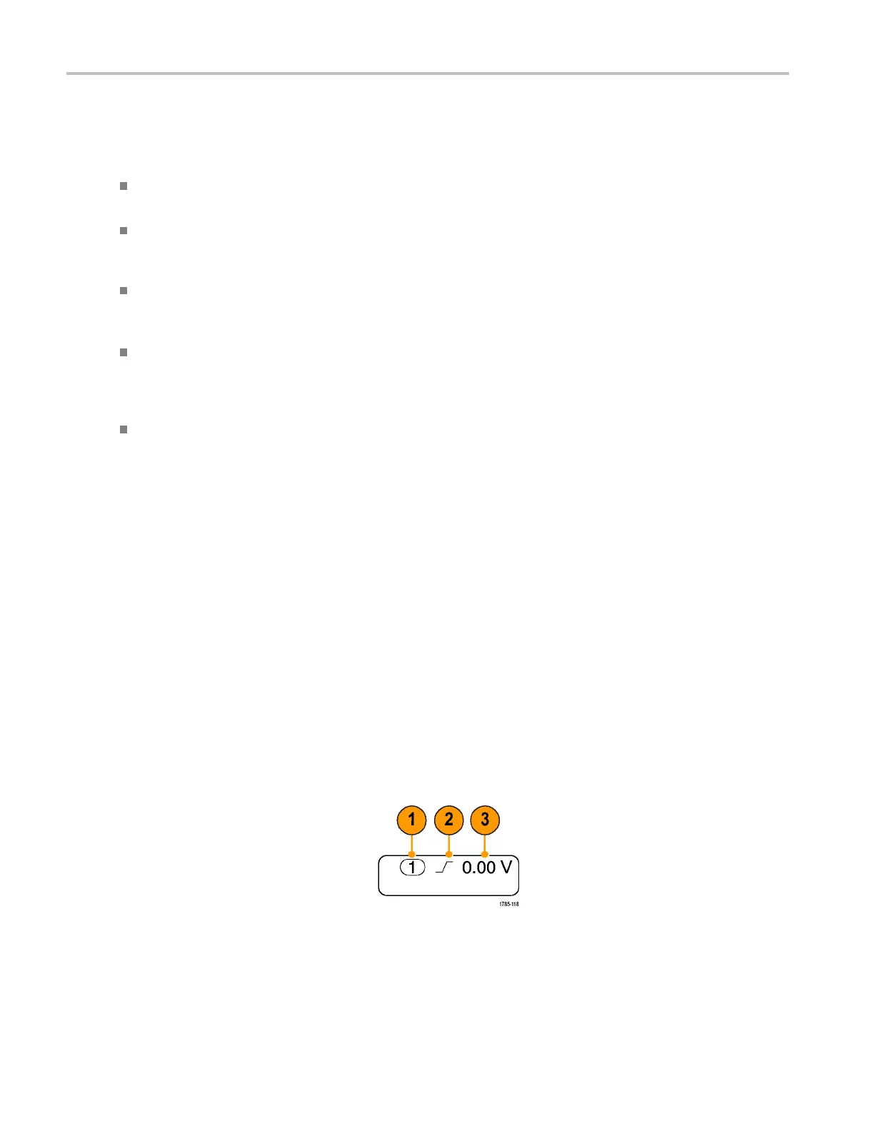
Checking Trigger Settings
To quickly determine the settings of some
key trigger parameters, check the Trigger
readout at the bottom of the display. The
readouts differ for edge and the advanced
triggers.
1. Trigger source = channel 1.
2. Trigger slope = rising.
3. Trigger level = 0.00 V.
Edge trigger readout
90 MDO4000 Series Oscilloscopes User Manual
 Loading...


