Logic Triggering
3–68
TDS 420A, TDS 430A, TDS 460A & TDS 510A User Manual
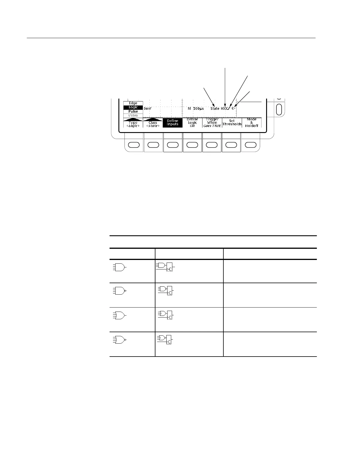
Trigger Class = State
Ch 1, 2, 3 Inputs = High, Don’t Care, High
Ch 4 Input = Rising Edge
Logic = OR
Figure 3–35: Logic Trigger Readouts
Definitions
Table 3–4 lists the definitions for the four types of logic functions available.
Keep in mind the following operating modes for the two classes, pattern and
state, of logic triggers as you apply the definitions.
Table 3–4: Logic Triggers
Pattern State Definition
1,2
AND Clocked AND If all the preconditions selected for the
logic inputs
3
are true, then the oscillo-
scope triggers.
NAND Clocked NAND If not all of the preconditions selected for
the logic inputs
3
are true, then the
oscilloscope triggers.
OR Clocked OR If any of the preconditions selected for
the logic inputs
3
are true, then the
oscilloscope triggers.
NOR Clocked NOR If none of the preconditions selected for
the logic inputs
3
are true, then the
oscilloscope triggers.
1
Note that for State class triggers, the definition must be met at the time the clock
input changes state. See the descriptions for Pattern and State in this section.
2
The definitions given here are correct for the Goes True setting in the Trigger When
menu. If that menu is set to Goes False, swap the definition for AND with that for
NAND and for OR with NOR for both pattern and state classes.
3
The logic inputs are channels 1, 2, 3, and 4 when using Pattern Logic Triggers. For
State Logic Triggers, channel 4 becomes the clock input.

 Loading...


