Delayed Triggering
3–14
TDS 420A, TDS 430A, TDS 460A & TDS 510A User Manual
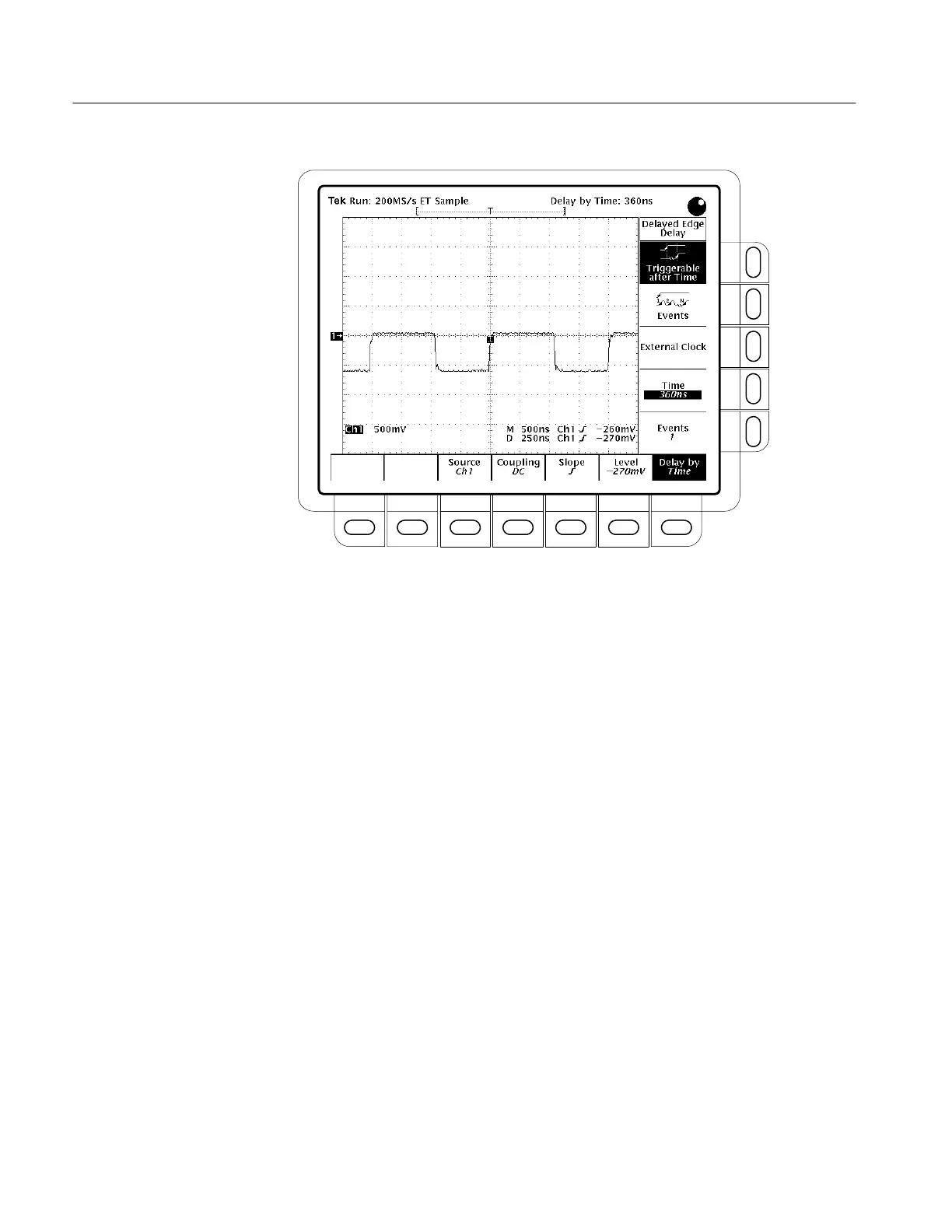
Figure 3–6: Delayed Trigger Menu (TDS 400A shown)
8. To define how the input signal is coupled to the delayed trigger, press
Coupling
(main) ➞ DC, AC, HF Rej, LF Rej, or Noise Rej (side). For
descriptions of these coupling types, see To Specify Coupling on page 3–23.
9. To select the slope that the delayed trigger occurs on, press Slope
(main).
Choose between the rising edge and falling edge slopes.
When using Delayed Triggerable mode to acquire waveforms, two trigger
bars are displayed. One trigger bar indicates the level set by the main trigger
system; the other indicates the level set by the delayed trigger system.
10. Press Level
(main) ➞ Level, Set to TTL, Set to ECL, or Set to 50% (side).
For a description of these level settings, see To Set Level on page 3–24.

 Loading...


