TROUBLESHOOTING
TESTING THE COMPONENTS
THE AIR SWITCH
Refer to page 2-24 to access the air switch.
1. With no power applied, remove the wire
connectors from the terminals.
2. Set the ohmmeter to the R x 1 scale.
3. Connect one of the ohmmeter leads to the
common (C) terminal of the switch (the termi-
nal callouts are stamped on the switch).
4. Touch the free ohmmeter lead to the N.O.
(normally-open) switch terminal. The meter
should show no continuity with the switch in
its normal position, and continuity when it is
activated.
5. If the readings are not correct, remove and
replace the switch.
WARNING
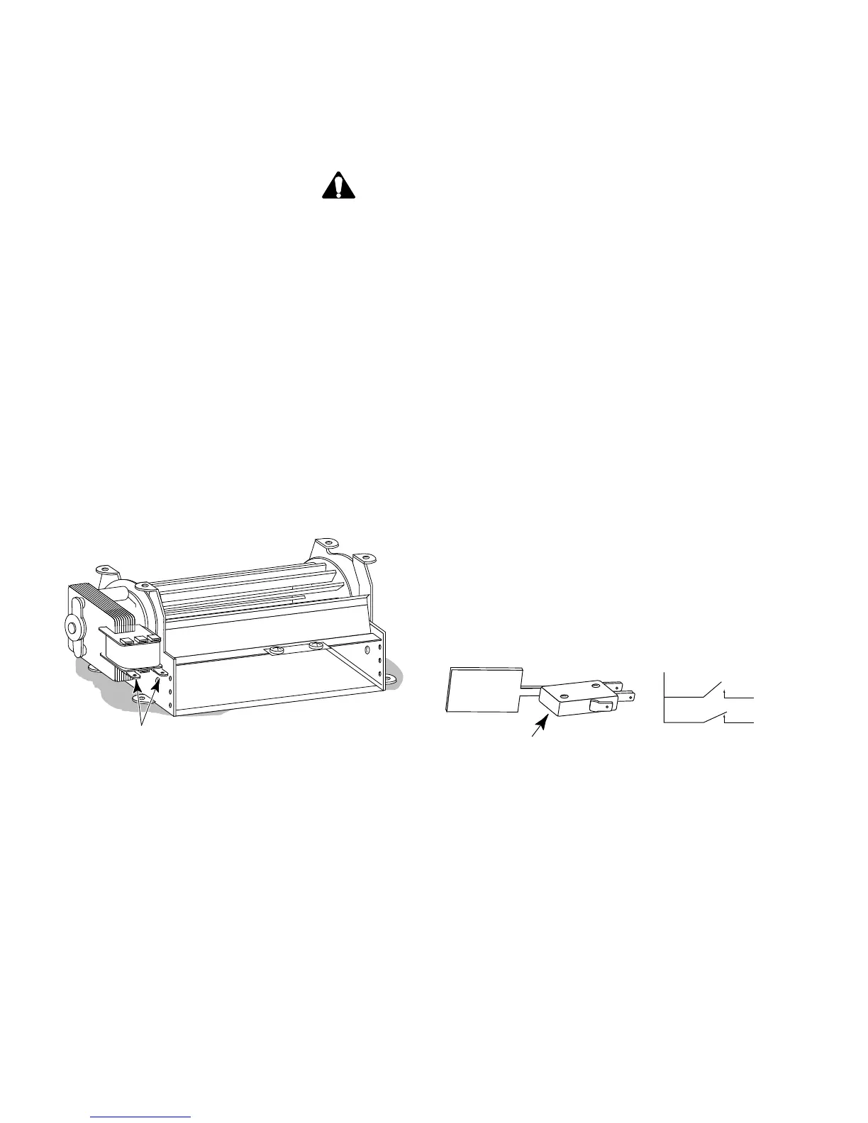
Motor Terminals
BLOWER ASSEMBLY
TO AVOID ELECTRICAL SHOCK
• DISCONNECT THE POWER TO THE APPLIANCE BEFORE SERVICING.
• FOR THOSE CHECKS REQUIRING THE USE OF ELECTRICAL POWER, EXERCISE EXTREME
CARE.
• DO NOT PERFORM HIGH-VOLTAGE TESTS.
THE BLOWER MOTOR
Refer to page 2-26 to access the blower motor.
1. With no power applied, disconnect the motor
wire connectors from their terminals.
2. Set the ohmmeter to the R x 1 scale.
3. Touch the ohmmeter leads to the motor ter-
minals. The meter should indicate 13 Ω.
4. If the reading is not correct, remove and re-
place the blower motor.
NO
NO
NC
Air Switch
COM
COM
NC
Page 48
 Loading...